


USING THE COMBISCOPE INSTRUMENTS 3 - 21
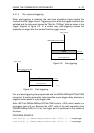
Trigger Slope
The TRIGger:SLOPe command allows you to define the trigger edge for all input
channels, which can be POSitive, NEGative, or EITHer. After a
*
RST command
the TRIGger:SLOPe is set to POSitive.
PROGRAM EXAMPLE:
CALL Send(0, 8, "CONFigure:PTPeak (@2)", 1) ’
Configures channel 2
CALL Send(0, 8, "SENSe:FUNCtion 'XTIMe:VOLTage2'", 1
)
’
Sets channel 2 ON
CALL Send(0, 8, "TRIGger:SOURce INTernal2", 1) ’
Trigger source = channel 2
CALL Send(0, 8, "TRIGger:LEVel 0.2", 1) ’
Trigger level = 0.2 V
'The TRIGger:LEVel command also switches level peak-peak off.
CALL Send(0, 8, "TRIGger:SLOPe NEGative", 1) ’
Trigger slope = negative
CALL Send(0, 8, "INITiate", 1) ’
Single initiation
CALL Send(0, 8, "FETCh:PTPeak? (@2)", 1) ’
Queries for peak-to-peak
response$ = " "
CALL Receive(0, 8, response$, 256) ’
Enters peak-to-peak
PRINT "Measured peak-to-peak = "; response$ ’
Prints peak-to-peak
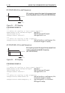
Trigger Coupling
The TRIGger:LPASs and TRIGger:HPASs commands allow you to select the
Main Time Base (MTB) trigger coupling by programming a fixed cutoff frequency.
The possible trigger coupling options
AC coupling
,
DC coupling
,
Low Frequency
reject
, and
High Frequency reject
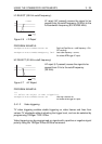
are mutually exclusive. The TRIGger:LPASs
and TRIGger:HPASs commands are also mutually exclusive. So, activating the
Low-Pass filter will switch off the High-Pass filter, and vice versa. After a
*
RST
command, the cutoff frequency is 10 Hertz, which selects trigger coupling AC.
Note: When the trigger source is INTernal<n>, signal coupling for one input
channel (n) can be programmed to AC, DC, or GROund using the
INPut<n>:COUPling command.