


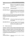

3 - 22 USING THE COMBISCOPE INSTRUMENTS
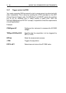
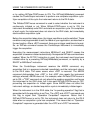
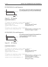
DC COUPLING (0 Hz cutoff frequency):
DC coupling causes the signal to be passed over
the full bandwidth (from 0 Hz to 60/100/200 MHz).
PROGRAM EXAMPLE:
***
*** Select DC coupling on input signal channel 2.
SENSe:FUNCtion:ON "XTIMe:VOLTage2"
Sets CH2 on.
INPut2:COUPling DC
Sets CH2 input signal DC coupled.
TRIGger:SOURce INTernal2
Sets trigger source = CH2.
***
*** Select DC coupling on MTB triggering.
TRIGger:FILTer:LPASs:STATe ON
Sets Low-Pass filter on + cutoff frequency = 0 Hz;
this selects MTB trigger DC coupling.
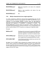
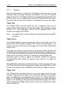
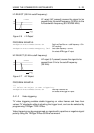
AC COUPLING (10 Hz cutoff frequency):
AC coupling causes the signal to be passed from
10 Hz to the full bandwidth frequency
(60/100/200 MHz).
PROGRAM EXAMPLE:
***
*** Select AC coupling on input signal channel 3.
SENSe:FUNCtion:ON "XTIMe:VOLTage3"
Sets CH3 on.
INPut3:COUPling AC
Sets CH3 input signal AC coupled.
TRIGger:SOURce INTernal3
Sets trigger source = CH3.
***
*** Select AC coupling on MTB triggering.
TRIGger:FILTer:LPASs:STATe ON
Sets Low-Pass filter on + cutoff frequency = 0 Hz;
this selects MTB trigger DC coupling.
TRIGger:FILTer:LPASs:FREQuency 10
Sets cutoff frequency = 10 Hz; this selects
MTB trigger AC coupling.
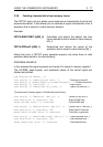
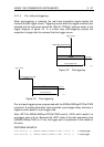
Figure 3.4 DC Coupling
FULL BANDWIDTHDC
DC COUPLING-3dB
0dB
FREQ.
S
T7427
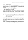
Figure 3.5 AC Coupling
FULL BANDWIDTH10Hz
AC COUPLING-3dB
0dB
FREQ.
ST7426