


3–6 EPM 6000 MULTI-FUNCTION POWER METERING SYSTEM – USER GUIDE
CHAPTER 3: INSTALLATION
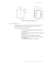
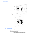
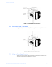
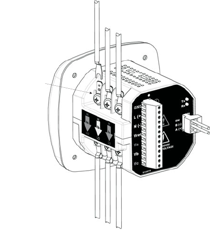
3.2.2 CT Leads Terminated to Meter
The EPM 6000 is designed to have current inputs wired in one of three ways. The figure
below shows the most typical connection, where CT Leads are terminated to the meter at
the current gills. This connection uses nickel-plated brass studs (current gills) with screws
at each end. This connection allows the CT wires to be terminated using either an “O” or a
“U” lug. Tighten the screws with a #2 Phillips screwdriver.
FIGURE 3–5: CT Leads Terminated to Meter
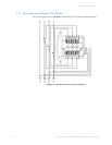
Wiring diagrams are detailed in Wiring Diagrams on page 3–9. Communications
connections are detailed in Communications Setup on page 3–19.
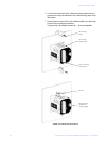
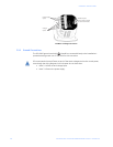
3.2.3 CT Leads Pass-Through (No Meter Termination)
The second method allows the CT wires to pass through the CT Inputs without terminating
at the meter. In this case, remove the current gills and place the CT wire directly through
the CT opening. The opening will accommodate up to 0.177" / 4.5 mm maximum diameter
CT wire.
Current gills
(nickel-plated
brass stud)