


CHAPTER 1: OVERVIEW
EPM 6000 MULTI-FUNCTION POWER METERING SYSTEM – USER GUIDE 1–3
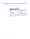
1.2 Features
1.2.1 Universal Voltage Inputs
Voltage Inputs allow measurement to 416 V line-to-neutral and 721 V line-to-line. This
insures proper meter safety when wiring directly to high voltage systems. One unit will
perform to specification on 69 V, 120 V, 230 V, 277 V, and 347 V systems.
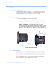
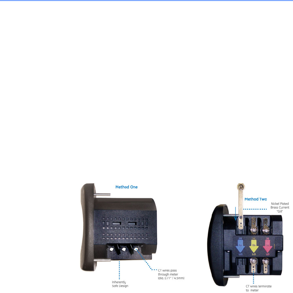
1.2.2 Current Inputs
The EPM 6000 current inputs use a unique dual input method.
• Method 1 – CT Pass Through: The CT passes directly through the meter without
any physical termination on the meter. This insures that the meter cannot be a
point of failure on the CT circuit. This is preferable for utility users when sharing
relay class CTs. No burden is added to the secondary CT circuit.
• Method 2 – Current “Gills”: This unit additionally provides ultra-rugged
termination pass-through bars that allow CT leads to be terminated on the meter.
This, too, eliminates any possible point of failure at the meter. This is a preferred
technique for insuring that relay class CT integrity is not compromised (the CT will
not open in a fault condition).
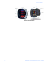
FIGURE 1–2: Current Input Connections
1.2.3 Utility Peak Demand
The EPM 6000 provides user-configured Block (fixed) or Rolling window demand. This
feature allows you to set up a customized demand profile. Block window demand is
demand used over a user-defined demand period (usually 5, 15, or 30 minutes). Rolling
window demand is a fixed window demand that moves for a user-specified subinterval
period. For example, a 15-minute demand using 3 subintervals and providing a new
demand reading every 5 minutes, based on the last 15 minutes.