


308–293 9
Setup
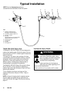
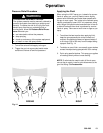
1. Connect the Air Line
NOTE:
D You
must install an air pressure regulator (F) on the
gun air line to control air pressure to the gun. See
Fig. 2.
D
If your regulated air source does not have a filter
,
install an air filter (G) on the air line to ensure a dry
,
clean air supply to the gun. Dirt and moisture can
ruin the appearance of your finished workpiece.
See Fig. 2.
D
Use a 5/16 inch (7.9 mm) I.D. air hose to minimize
excessive pressure drop in the hose.
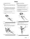
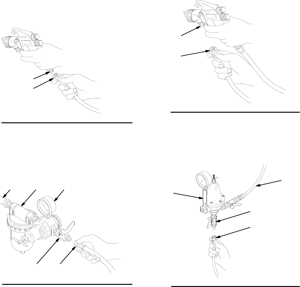
A.
Connect the air hose (D) to the 1/4 npsm gun air
inlet (C).
D
C
02051
Fig. 1
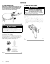
B.
Connect the other end of the air hose (D) to a reg
-
ulated air supply line (H).
NOTE:
Fig. 2 shows the filter (G) air regulator (F),
and air shut-of
f valve (E) on the air supply line.
01990
D
FG
Fig. 2
H
E
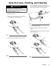
2. Connect the Fluid Hose
NOTE:
D Before
connecting the fluid line, blow it out with air
and flush it with solvent. Use solvent which is
compatible with the fluid to be sprayed.
D
Install a fluid regulator (L) on the fluid line to control
fluid pressure to the gun. See Fig. 4.
D
Filter the fluid line of coarse particles and sediment
to avoid clogging the fluid nozzle and causing
finishing defects.
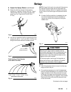
A.
Connect the fluid hose (J) to the gun fluid inlet (B)
3/8–18 npsm [R 3/8–19] compound thread.
J
B
02052
Fig. 3
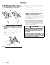
B.
Connect the other end of the fluid hose (J) to a
regulated fluid supply line (K).
NOTE:
Fig. 4 shows the fluid regulator (L) and
fluid shut-of
f valve (M) on the fluid supply line (K).
J
L
02054
Fig. 4
K
M