


12
307-712
MAINTENANCE
To
C
lea
n o
r C
hang
e A
i
r C
a
p a
n
d F
lui
d N
ozzle
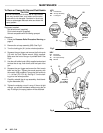
CAUTION
Do
not use metal tools to clean the air cap holes as
this may scratch them, and make sure the elec-
trode
wire is not damaged. Scratches in
the air cap
holes
or a damaged electrode wire can distort the
spray
pattern.
Equipment needed:
Soft bristle brush (supplied).
Fluid nozzle wrench (supplied).
Solvent compatible with fluid being sprayed.
Procedure:
1. Follow
the
Pressure Relief Procedure W
arning
on
page
9.
2.
Remove the air cap assembly (BB). See Fig 6.
3. T
urn the locking pin (81) to the unlocked position.
4. Squeeze
the gun trigger and remove the fluid nozzle
(15) with the fluid nozzle wrench (66g) supplied.
Make
sure the front of the gun is pointed down. See
Fig
6.
5. Use
the soft bristle
brush (66a) supplied and solvent
to
clean the air cap, fluid nozzle, and front part of the
gun.
6. Squeeze the gun trigger and screw the fluid nozzle
back into the gun. Tighten the nozzle securely with
the
wrench (66g) supplied. T
orque the fluid nozzle to
1.1–1.4
N
S
m (10–12
in–lb). See Fig 6. T
urn the lock
-
ing
pin to the locked position.
7. Carefully
reinstall the air cap assembly
. A
void bend
-
ing
the electrode (CC).
8. Tighten
the retaining nut so it is snug. If the nut is
tight
enough,
you will feel resistance when turning the air
cap.
If too tight, the spray pattern will be distorted.
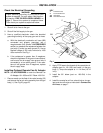
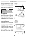
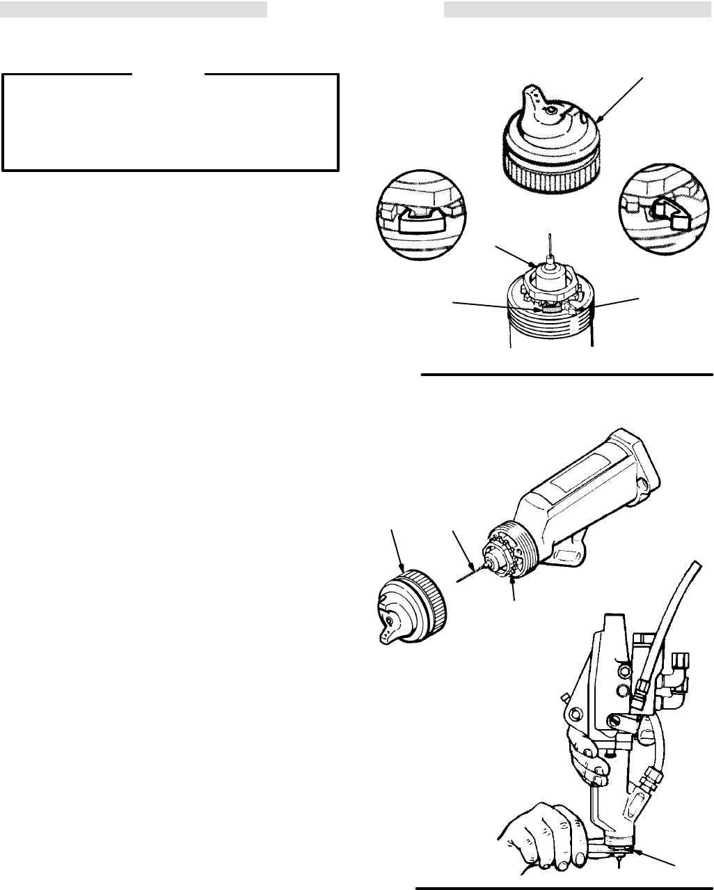
Fig 5
KEY
15 Fluid
Nozzle
BB
Air Cap Assembly
81
Locking Pin
BB
15
Locked
Position
Unlocked
Position
DETAIL
DETAIL
81
81
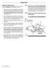
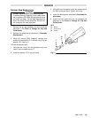
Fig
6
KEY
CC Electrode
15 Fluid
Nozzle
16
Air Cap Assembly
66g Wrench
CC
15
16
T
orque to
1.1–1.4 N
Sm
(10–12 in–lb)
66g