


23
307-712
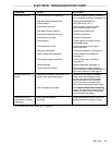
SERVICE
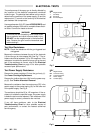
Turbine Alternator Removal
1. Remove power cartridge from the gun body as
described under Power Cartridge Replacement.
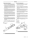
2. Carefully twist the turbine alternator (2a) counterĆ
clockwise and pull it off the power supply (5) until
just disengaged from the coupling. Then continue
to slowly pull the turbine alternator away from the
power supply, disconnecting the 3Ćwire connector
(HH). See Fig 19.
3. Using an ohmmeter, test the coil in the turbine alterĆ
nator (2a). Measure the resistance between the two
outer terminals of the 3Ćwire connector (HH). The
resistance should be 3 to 5 ohms. If the reading varĆ
ies from this value, replace the alternator.
4. Measure the resistance between each outer termiĆ
nal of the 3Ćwire connector (HH) and the turbine alĆ
ternator housing. The resistance should be infinite.
If the resistance is not infinite, replace the alternator.
5. Partially connect the 3Ćwire connector (HH) onto the
prongs inside the power supply (5). See Fig 19. UsĆ
ing a small screwdriver, push the connector onto the
prongs until seated.
6. Slide the turbine alternator (2a) onto the power supĆ
ply, being sure to align the coupling between the
power supply and the turbine alternator housing.
Then twist the turbine alternator clockwise to lock
the coupling.
7. Install the power cartridge in the gun body as
described under Power Cartridge Replacement.
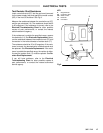
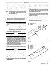
Fig 19
KEY
HH 3-wire Connector
2a Alternator
5 Power Supply
5
HH
2a
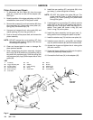
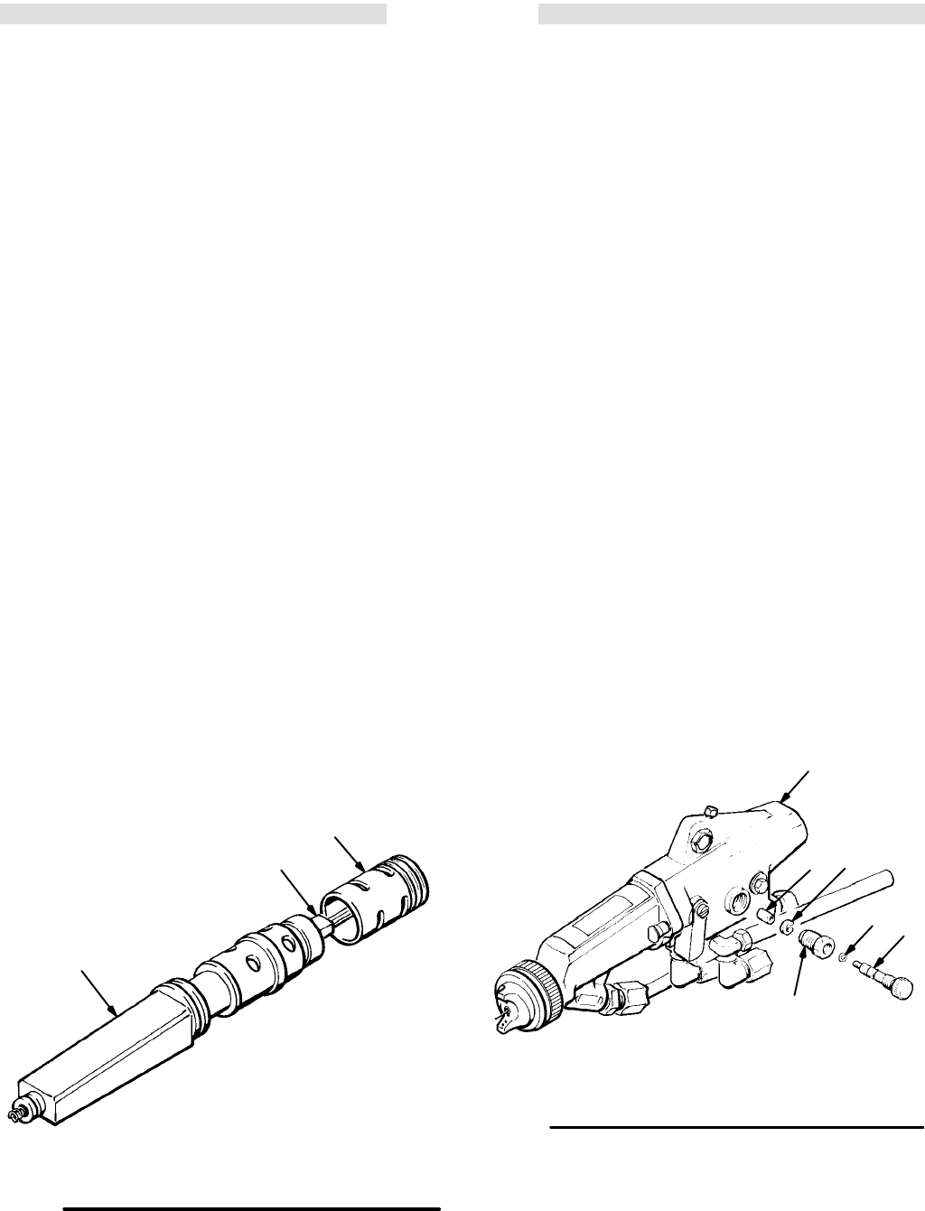
Fan Air Valve Replacement
1. Place a wrench on the flats of the valve housing (55)
and remove it from the gun body (1). See Fig 20.
2. Remove the retaining ring (46).
3. Rotate the air adjusting screw (56) counterclockĆ
wise until it is disengaged from the valve housing
threads. Pull the adjusting screw out of the valve
housing (55).
4. Clean all the parts and inspect them for wear or
damage. If replacing the seal (47), unscrew it clockĆ
wise and remove it from the adjusting screw.
5. Apply medium grade thread sealant to the small
threads on the end of the adjusting screw (56) and
install a new seal (left hand thread).
6. When reassembling the fan air valve, lubricate the
o-ring (54) and the adjusting screw threads with
petroleum jelly.
7. After the retaining ring (46) is installed on the adjustĆ
ing screw (56), back the adjusting screw out of the
valve housing (55) until it bottoms out against the reĆ
taining ring.
8. Apply Teflonr paste to the threads of the valve housĆ
ing (55) and install it in the gun body (1). Torque the
housing to 1.1-1.4 NSm (10-12 in-lb).
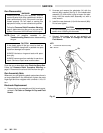
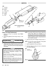
Fig 20
KEY
1 Gun Body
46 Retaining Ring
47 Valve Seal
54 OĆRing
55 Valve Housing
56 Adjusting Screw
47 46
56
55
1
54
Apply Teflon paste.
Torque to
1.1-1.4 NSm
(10-12 in-lb)