


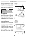
24
307-712
SERVICE
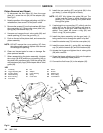
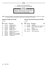
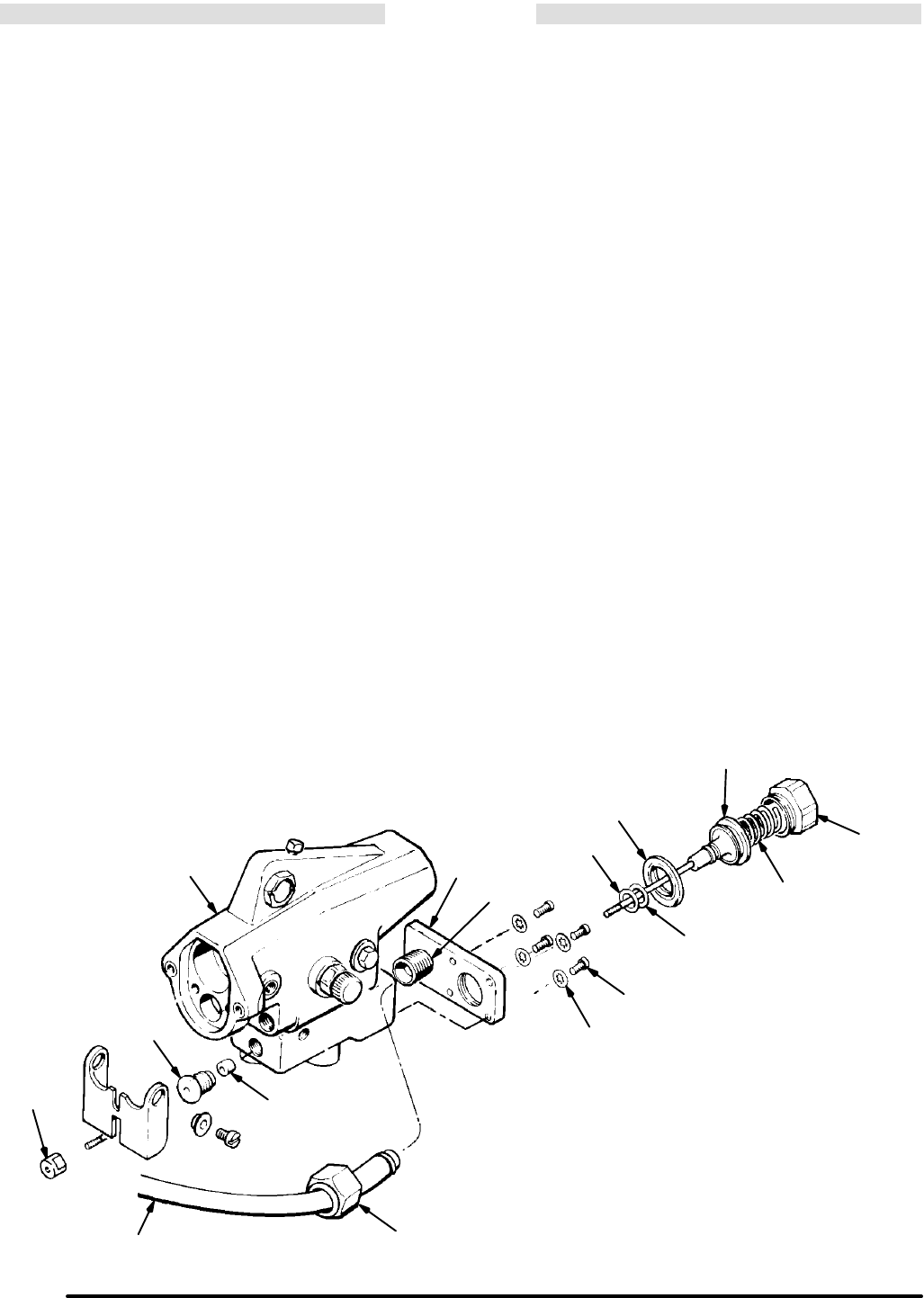
Piston Removal and Repair
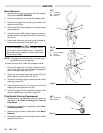
1. To disconnect the fluid hose (31) from the cover
plate (41), screw the nut (34) off the adapter (35).
See Fig 21.
2. Note the position of the trigger adjusting nut (24) for
reinstallation, then screw it off the piston shaft.
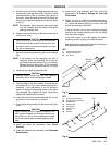
3. Remove the screws (61) and lock washers (82) from
the cover plate (41). Remove the cover plate (41),
spring (38), and retainer cap (74).
4. Unscrew and remove the air valve guide (26) and
needle packing (27) from the gun body (1),
5. Push on the end of the piston shaft, and remove the
piston assembly.
NOTE: DO NOT remove the uĆcup packing (37) from
the piston shaft except to replace it as removal
will damage this packing.
6. Clean and inspect parts for wear or damage. ReĆ
place parts as needed.
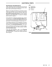
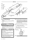
7. When reassembling the piston assembly, lubricate
the oĆrings (30 & 79) and the uĆcup packing (42) on
the piston with petroleum jelly. Pack the spring (38)
with petroleum jelly. Apply Teflon tape to the air valve
guide (26).
8. Install the new packing (27) and guide (26) in the
gun body (1); screw the guide in loosely.
NOTE: DO NOT fully tighten the guide (26) yet. The
guide must be loose to avoid damaging the
packing (27) when pushing the piston shaft
through the guide.
9. If replacing the uĆcup packing (37), slide it onto the
piston (42) so the lips of the packing will face toĆ
wards the front of the gun when the piston is inĆ
stalled. Then install the bunaĆn oĆring (30) and
Vitonr oĆring (79) on the piston.
10. Install the piston assembly into the gun body (1),
being careful not to damage the piston's lip seal.
11. Install the retainer cap (74) into the cover plate (41).
12. Install the cover plate (41), spring (38), and retainer
cap (74) with the screws (61) and lock washers (82).
13. Actuate the trigger and tighten the air valve guide
(26) with a wrench.
14. Screw the trigger adjusting nut (24) onto the piston
shaft to its previously noted position.
15. Connect the fluid hose (31) to the adapter (35).
Fig 21
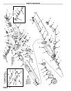
KEY
1 Gun Body
24 Trigger Adjusting Nut
26 Air Valve Guide
27 Needle Packing
30 BunaĆn OĆRing
31 Fluid Tube
34 Nut
35 Adapter
37 UĆCup Packing
38 Spring
41 Cover Plate
42 Piston
61 Screws
74 Retainer Cap
79 Viton OĆRing
82 Lock Washers
26
Apply
Teflon
tape
24
31
34
27
41
35
82
61
30
79
37
38
74
Pack with
lubricant
42
1