


8
307-712
INSTALLATION
Check the Electrical Grounding
WARNING
Proper electrical grounding of every part of your
system
is
essential. For your safety
, read the warn
-
ing section, FIRE OR EXPLOSION HAZARD, on
page 5. Ground the system as explained there.
Then
check your system as explained below
.
1.
Shut of
f all air lines to the gun.
2.
Shut of
f the fluid supply to the gun.
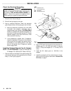
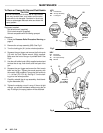
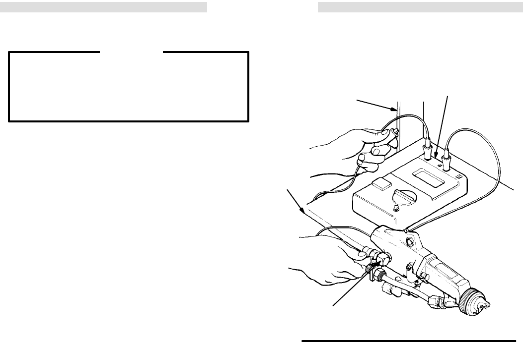
3. Have a qualified electrician check the electrical
grounding
continuity of the spray gun and air hose.
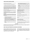
a. With the electrically conductive air hose (BB)
connected and properly grounded, use a
megohmmeter (AA) (shown in ACCESSORIES
section)
to measure the resistance between the
gun
body (Y) and a true earth ground (Z). Use
an
applied voltage of 500 volts
minimum
to 1000
volts
maximum
. See Fig 1.
b. If the resistance is greater than 2 megohms,
check the tightness of the ground connections,
and be sure the air supply hose ground wire is
connected to a true earth ground. If the resis-
tance is still greater than 2 megohms, replace
the
air supply hose.
Installing
Optional Remote Fan Air
Adapter
NOTE: See ACCESSORIES to order the Remote Fan
Air
Adapter 181–053 and 90
_
Elbow 108–234.
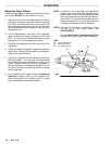
1. Place
a wrench on the flats of the valve housing (55)
and
remove the
fan air valve assembly from the gun
body
(1). See Fig 20, page 23.
Fig 1
KEY
Y Turbine
Air Inlet
Z T
rue Earth Ground
AA Ohmmeter
BB
Grounded Air Hose
Z
Y
AA
BB
2. Apply
PTFE
tape to the threads of the remote fan air
adapter (part no. 181–053) and install it in the gun
body
(1). T
orque the adapter to 1.1–1.4 N
S
m (10–12
in-lb).
3. Install the 90_ elbow (part no. 108–234) in the
adapter.
4. Install
the remote fan air line, solenoid valve, air regu
-
lator
and shut-of
f valve as instructed in
Connect the
Air Lines
, on page 7.