


9
307-712
OPERATION
WARNING
Pressure Relief Procedure
To reduce the risk of serious bodily injury, including
splashing
in the eyes or on the skin, injury from
moving
parts or electric shock, always follow this procedure
when
shutting of
f the system, when checking or serv
-
icing any part of the spray system, when installing,
cleaning
or changing
fluid nozzles, and whenever you
stop
spraying.
1. Turn off all the air to the gun except the cylinder
(actuating)
air.
2. T
urn of
f the fluid supply to the gun.
3. Trigger
the gun into a
grounded
metal waste con
-
tainer
to relieve fluid pressure.
4.
Engage the gun safety latch.
5. Open the pump drain valve, having a waste con-
tainer
ready to catch the drainage.
6. Leave the pump drain valve open until you are
ready
to spray again.
Operating Checklist
Check
the following list daily
, before
starting to operate
the system, to help ensure you of safe, efficient
operation.
1. Be sure all operators are properly trained to
safely
operate an automatic air spray system.
2.
Be sure all operators are trained how
to
prop
-
erly
and completely relieve system pressure.
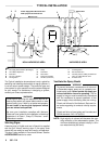
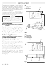
3. Be sure the system is thoroughly grounded.
See FIRE OR EXPLOSION HAZARD, page
5, and Check the Electrical Grounding,
page 8.
4. Be
sure the operator and all persons entering
the
spray area are properly grounded by
wear
-
ing shoes with conductive soles or personal
grounding
straps.
5. Be sure ventilation fans are operating prop-
erly.
6. Be
sure the work piece hangers are clean and
grounded. Contact points must be sharp
points
or knife edges.
7. Be sure all refuse is removed from the spray
booth.
8. Be sure all flammable liquids in the spray
booth
are in approved, grounded containers.
9. Be sure all conductive objects within 6 m
(20 ft)
of the gun are electrically grounded and
the floor of the spray area is electrically con-
ductive
and grounded.
Filter the Fluid
Filter the fluid to remove coarse particles and sediment
which
could clog the spray nozzle.
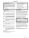
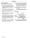
Spraying Operation
This gun has a built-in lead and lag operation. The gun
begins emitting air before the fluid is discharged. When
you
release the trigger
, the fluid
stops before the air flow
stops.
This helps prevent fluid build-up on the air cap.
Adjust the system’s control device, if it is automatic, so
the gun starts spraying just before meeting the work
piece,
and stops as soon as the work
piece has passed.
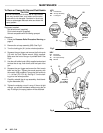
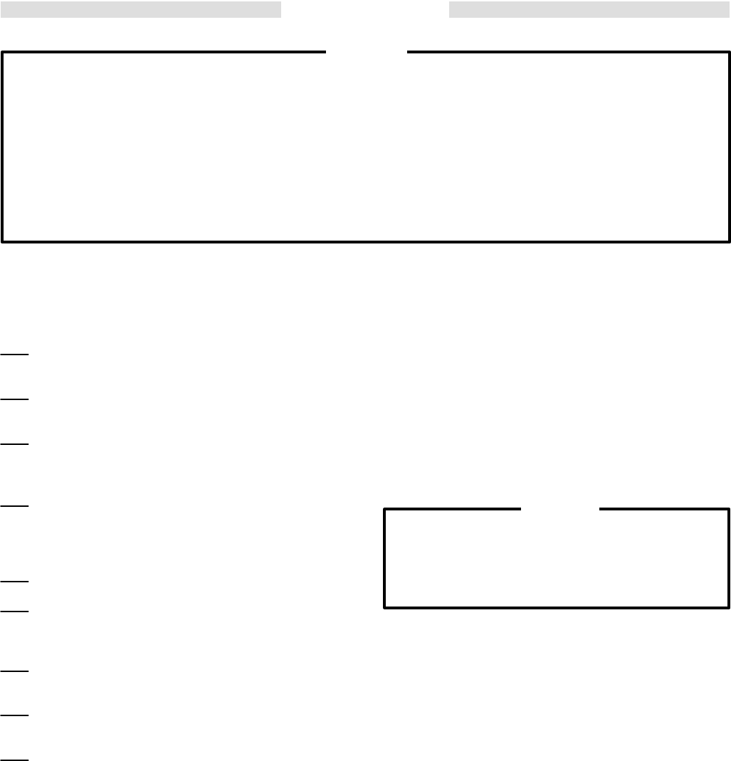
When
spraying, the ES indicator lights (BB) should glow
,
indicating
the electrostatic charge. See Fig 4.
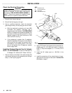
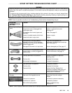
Selecting a Fluid Nozzle and Air Cap
WARNING
To
reduce the risk
of serious bodily injury
, including
splashing in the eyes or on the skin or electric
shock, always follow the Pressure Relief Proce-
dure,
above, before installing, or
removing the fluid
nozzle/air
cap assembly
.
This
gun is supplied with fluid nozzle 181–299 and air cap
180–739. See Instruction Manual 307–803 for air cap
consumption
and fluid nozzle flow rate information.
The
fluid output and pattern shape depends on the fluid
nozzle size, fluid viscosity, and fluid pressure. If your
application
requires a dif
ferent
nozzle and air cap combi
-
nation, use manual 307–803 to select the appropriate
fluid
nozzle and air cap.
To
install a dif
ferent fluid
nozzle and air cap, see
T
o Clean
or
Change Air Cap and Fluid Nozzle
, page 12.