


11307741
Service
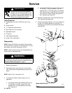
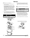
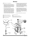
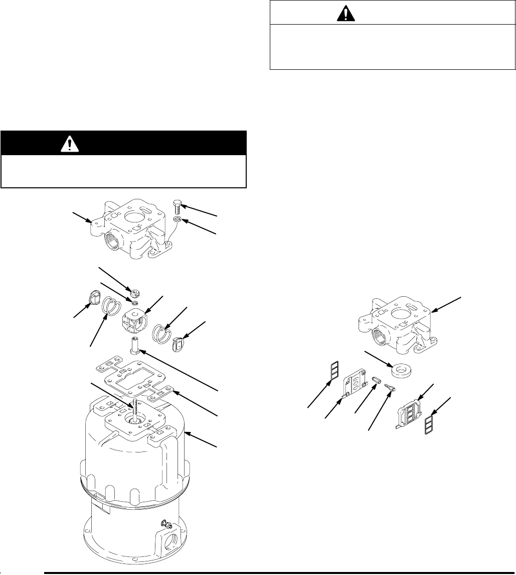
NOTE: Refer to Fig. 4 for steps 6 to 11.
6. Remove the screws (31) and lockwashers (13)
from the manifold (20).
7. To prevent the spring-loaded director valves
(3) from popping out, carefully lift the manifold
(20) up about 51 mm (2 in.) from the cylinder (36).
Place one hand under the manifold to hold the
director valves in the valve housing (5), then
continue lifting the manifold. Remove your hand
slowly, allowing the valve springs to release gently.
Inspect the director valves (3) and compression
springs (4).
8. Turn the manifold (20) over. Place wrenches on
the flats of the adjusting screw (11) and nut (12)
and turn the screw further into the nut until you can
remove it. Do this in all four positions.
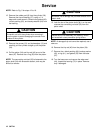
WARNING
The openings in the valve plates (2) are very sharp.
Be careful not to cut yourself.
9. Remove and check the valve plates (2), handling
them carefully. Clean the plates and mating sur-
faces of the manifold (20). Remove the rubber pad
(8).
NOTE: If you replace the valve plates, also replace the
seals (1).
CAUTION
Be careful not to damage the surface of the trip rod
(40), which would restrict its free movement. Special
padded pliers, 207579, are available.
10. Pull the trip rod (40) up and grasp it with the
padded locking pliers (order 207579). Hold the
flats of the valve housing hub (10) with a wrench,
screw off the trip rod nut (7) and remove the air
valve housing (5). Remove the lockwasher (6) and
screw off the hub (10). Now release the pliers.
11. Remove the gasket (38) from the air cylinder (36).
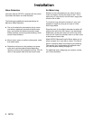
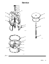
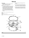
07282A
Fig. 4
20
11
12
8
2
1
Detail of Air Manifold and Valve Plates
31
13
36
3
4
10
7
6
5
38
40
4
3
20
1
2