


307912 7
Installation
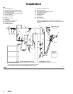
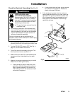
Connect the Air Line (Refer to Fig. 1)
WARNING
ELECTRIC SHOCK HAZARD
To reduce the risk of an electric shock or
other serious injury, the air supply hose
must be electrically connected to a true
earth ground. Use Only Graco Electrically Con-
ductive Air Supply Hose.
1. Connect the Graco Electrically Conductive Air
Supply Hose (R) between the air supply line and
the gun’s air inlet (V). The gun air inlet fitting has a
left hand thread. Connect the air supply hose
ground wire to a true earth ground.
2. Install an air line filter (O) and an air and water
separator (D) on the air line to ensure a dry, clean
air supply to the gun. Dirt and moisture can ruin
the appearance of your finished workpiece and can
cause the gun to malfunction.
3. Install a bleed-type air regulator (G) on the pump
and gun air supply lines to control air pressure to
the pump and gun.
4. Install a bleed-type air shutoff valve on the main air
line (C) and the pump air line (E) to shut off air to
the pump. Install an additional bleed-type valve on
each pump air supply line to relieve air trapped
between this valve and the pump after the air
regulator is shut off.
WARNING
PRESSURIZED EQUIPMENT HAZARD
The bleed-type air shutoff valve is required in your
system to relieve air trapped between this valve
and the pump after the air regulator is closed.
Trapped air can cause the pump to cycle unexpect-
edly, which could result in serious injury, including
splashing in the eyes or on the skin.
5. Install an air line lubricator (F) as close to the
pump (H) as possible.
6. Install an air shutoff valve (P) on each gun air
supply line to shut off air to the gun(s).
Connect the Exhaust Tube
Press the exhaust tube (provided) onto the barbed
adapter on the bottom of the gun handle. Secure the
tube with the clamp provided. Refer to page 34.
Connect the Fluid Line (Refer to Fig. 1)
1. Before connecting the fluid line (N), blow it out with
air and flush it with solvent. Use solvent which is
compatible with the fluid to be sprayed.
2. Install a fluid regulator (M) on the fluid line to
control fluid pressure to the gun.
3. Install a fluid filter (K) and drain valve (U) at the
pump outlet.
WARNING
PRESSURIZED EQUIPMENT HAZARD
The fluid drain valve (U) is required in your system
to assist in relieving fluid pressure in the displace-
ment pump, hose and gun; triggering the gun to
relieve pressure may not be sufficient. Install a
drain valve close to the pump’s fluid outlet. The
drain valve reduces the risk of serious injury,
including splashing in the eyes or on the skin.
4. Connect the fluid line to the 3/8–18.6(m) gun fluid
inlet (W).
5. Before running any paint through the spray gun,
flush it out with a compatible solvent.