


308584 11
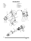
Installation
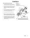
Install the Air Line Accessories
1. Install an air line filter and an air and water separa-
tor on the main air supply line to ensure a dry,
clean air supply to the gun. Dirt and moisture can
ruin the appearance of your finished workpiece
and can cause the gun to malfunction.
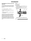
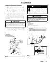
2. Install a bleed-type air regulator (A) on the pump
and gun air supply lines to control air pressure to
the pump and gun. Refer to Fig. 3, page 10.
3. Install a bleed-type air shutoff valve on the main air
line, the pump air line (to shut off air to the pump),
and the gun air line (B) (to shut off air to the gun).
WARNING
PRESSURIZED EQUIPMENT HAZARD
Trapped air can cause the pump to cycle or the
gun to spray unexpectedly, which could result in a
serious injury, including splashing in the eyes or on
the skin. The bleed-type air shutoff valve is re-
quired on the main air supply line so trapped air will
be relieved between this valve and the pump after
the air regulator is closed.
Connect the Air Line
WARNING
ELECTRIC SHOCK HAZARD
To reduce the risk of an electric shock or
other serious injury, you must use the
red-colored Graco Electrically Conduc-
tive Air Hose for the gun air supply hose, and you
must connect the hose ground wire to a true earth
ground. Do not use the black or grey-colored Graco
air hoses.
Connect the red-colored Graco Electrically Conductive
Air Hose (H) to the gun air inlet and connect the hose
ground wire (M) to a true earth ground (N). Refer to
Fig. 3, page 10. Check the electrical grounding of the
gun as instructed on page 15. See page 48 to order
the air hose.
NOTE: The hose and the gun have special left-hand
threads to prevent connecting another type of air hose
to the gun air inlet.
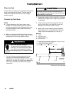
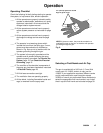
Connect the Exhaust Tube
Press the exhaust tube (provided) onto the barbed
adapter on the bottom of the gun handle. Secure the
tube with the clamp provided. Refer to page 46.
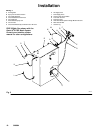
Install the Fluid LIne Accessories
1. Before connecting the fluid line, blow it out with air
and flush it with water.
2. A fluid regulator (C) is needed in the fluid line to
control fluid pressure to the gun. Refer to Fig. 3,
page 10.
NOTE: The H
2
O PRO voltage block comes with a fluid
regulator already installed.
3. Install a fluid filter and drain valve at the pump
outlet.
WARNING
PRESSURIZED EQUIPMENT HAZARD
To reduce the risk of serious injury, including
splashing in the eyes or on the skin, install a fluid
drain valve close to the pump’s fluid outlet. The
fluid drain valve is required in your system to assist
in relieving fluid pressure in the displacement
pump, hose and gun; triggering the gun to relieve
pressure may not be sufficient.