


12 308584
Installation
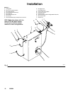
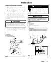
Filter the Fluid
Filter the fluid to remove coarse particles and sediment
which could clog the fluid nozzle. The filter must be
installed at the grounded fluid inlet to the voltage
isolation system.
Connect the Fluid Hose
NOTE:
D A Graco waterborne fluid hose must be used
between the voltage isolation system fluid outlet
and the spray gun fluid inlet. See page 48 to order
the Graco waterborne fluid hoses and the hose
replacement parts.
D Before connecting the fluid supply line to the gun,
blow it out with air, and flush it with water to remove
contaminants. Flush the gun before using it.
WARNING
ELECTRIC SHOCK HAZARD
To reduce the risk of an electric shock,
install only one continuous Graco water-
borne fluid hose between the isolated
fluid supply and the spray gun. Do not splice hoses
together.
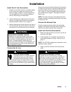
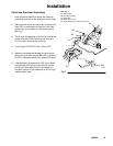
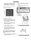
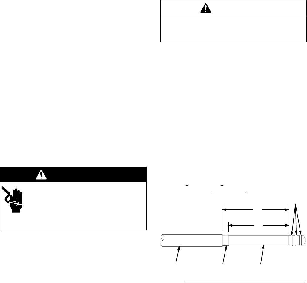
1. For the fluid hose to seal properly and be held
securely, the hose must be stripped and as-
sembled to the dimensions shown in Fig. 4. Refer
also to Fig. 29, page 42. A new Graco waterborne
fluid hose comes fully assembled to the proper
dimensions.
CAUTION
Be careful not to cut into the inner hose layer (K)
when stripping the hose. Nicks or cuts in the tube will
cause premature hose failure.
2. Inspect the condition of the o-rings (G) on the hose
barbed-fitting. Replace the o-rings if they are worn
or damaged.
3. Unscrew the hose ferrule housing (79) from the
gun fluid inlet fitting, and slide the nut onto the
barbed-end of the hose. Refer to Fig. 5.
4. Apply a light coat of dielectric grease (supplied
with the gun) to the o-rings (G) and to the entire
length of the inner hose layer (K). See Fig. 4.
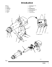
KEY- Fig. 4
G O-Rings
H Outer Hose Jacket
J Conductive Hose Layer
K Inner Hose Layer
Fig. 4
G
HJK
05342
Spray Gun
Hose End
Apply a light coat of dielectric grease to the o-rings (G) and the
entire length of the inner hose layer (K)
4.075 + 0.10 in. (103.5 + 2.5 mm)
Minimum of 4.375 + 0.10 in. (111.1 + 2.5 mm)
Continued on the next page