


18 308584
Operation
Operating the Spray Gun
WARNING
FIRE AND EXPLOSION HAZARD
To reduce the risk of fire and explosion,
only use this equipment to spray non-
flammable, waterborne fluids as defined
on the front cover of this manual.
WARNING
ELECTRIC SHOCK HAZARD
Contact with the charged components of
the spray gun will cause an electric
shock. Do not touch the gun nozzle or
electrode or come within 4 inches (101.6 mm) of
the front of the gun during gun operation or until
after following the Fluid Voltage Discharge and
Grounding Procedure on page 16.
Follow the Fluid Voltage Discharge and Ground-
ing Procedure on page 16 when you stop spray-
ing and whenever you are instructed to discharge
the voltage.
WARNING
PRESSURIZED EQUIPMENT HAZARD
To reduce the risk of an injury, follow the Pressure
Relief Procedure on page 16 when you stop
spraying, before installing or cleaning the fluid
nozzle, and whenever you are instructed to relieve
the pressure.
WARNING
COMPONENT RUPTURE HAZARD
To reduce the risk of component rupture,
which can cause serious injury, do not
exceed the maximum working pressure
of the lowest rated system component. This equip-
ment has a 100 psi (0.7 MPa, 7 bar) maximum
working air and fluid pressure.
Follow the steps below to establish the correct fluid
flow and air flow. Do not turn the ES ON-OFF lever to
ON yet:
1. Follow the Operating Checklist on page 17.
2. Make sure the system voltage is discharged.
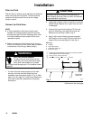
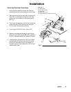
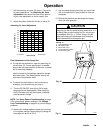
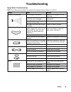
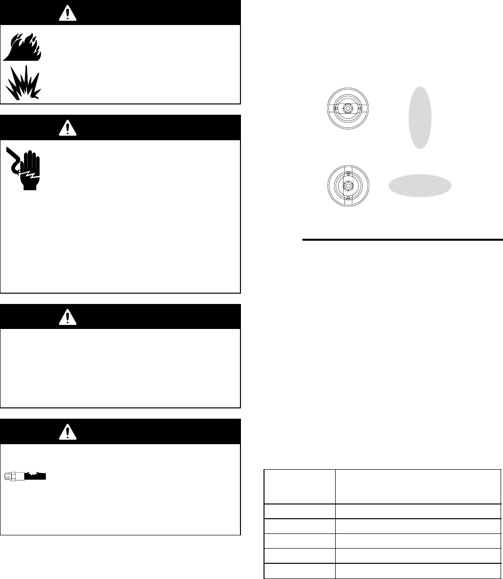
Loosen the air cap retaining nut, and rotate the air
cap for a vertical or horizontal spray pattern. See
Fig. 9. Then tighten the retaining nut until the air
cap is held firmly in place; you should not be able
to rotate the air cap horns by hand.
Fig. 9
02020
Horizontal Pattern
Vertical Pattern
3. Pressurize the fluid supply, and adjust the fluid
flow by using the fluid pressure regulator installed
in the fluid line. Refer to instruction manual 307803
to set the fluid pressure for various fluid flows,
according to the size of the fluid nozzle being
used.
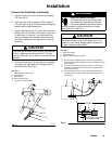
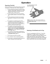
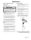
4. If necessary, further adjust the fluid flow rate with
the fluid adjustment knob (J). See Fig. 10.
5. Fully open the fan air valve (P).
6. Set the air pressure with the air pressure regulator.
The following chart shows the air hose inlet pres-
sure required to get full voltage from the power
supply. To avoid shortening the turbine life, do not
exceed the recommended air pressures.
Air Hose
Length
ft. (m)
Dynamic pressure at air hose inlet
required for full voltage
psi (kPa, bar)
15 (4.6) 45 to 50 (314 to 345, 3.1 to 3.4)
25 (7.6) 50 to 55 (345 to 379, 3.4 to 3.7)
50 (15.3) 60 to 65 (410 to 444, 4.1 to 4.4)
75 (22.9) 68 to 73 (465 to 501, 4.5 to 5.0)
100 (30.5) 75 to 80 (514 to 550, 5.1 to 5.5)