


28 308584
Electrical Tests
WARNING
ELECTRIC SHOCK HAZARD
Follow the Fluid Voltage Discharge
and Grounding Procedure on page 16
before checking or servicing and when-
ever you are instructed to discharge the voltage to
ensure the voltage is discharged and avoid serious
injury from an electric shock.
WARNING
PRESSURIZED EQUIPMENT HAZARD
To reduce the risk of an injury, follow the Pressure
Relief Procedure on page 16 before checking or
servicing the gun and whenever you are instructed
to relieve the pressure.
WARNING
FIRE, EXPLOSION, AND
ELECTRIC SHOCK HAZARD
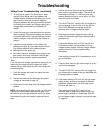
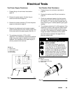
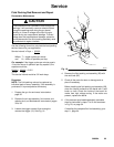
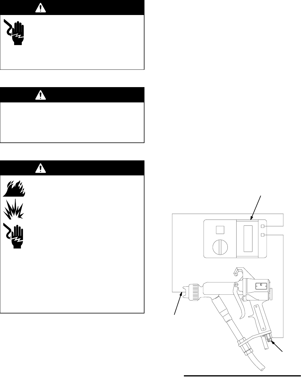
Megohmmeter P/N 218979 (A-see Fig.
13) is not approved for use in a hazard-
ous area. To reduce the risk of sparking,
do not use the megohmmeter to do
electrical tests unless:
D The gun has been removed from the
hazardous area;
D Or all spraying devices in the hazardous area
are turned off, ventilation fans in the hazardous
area are operating, and there are no flammable
vapors in the area (such as open solvent con-
tainers or fumes from spraying).
Failure to follow this warning could cause fire,
explosion, electric shock and result in serious injury
and property damage.
The performance and safety of the spray gun are
directly affected by the condition of the electrical
components contained inside the gun. The electrical
tests can be used to determine the condition of the
power supply (18) and the resistor stud (22) as well as
the continuity of the electrical path between the com-
ponents.
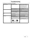
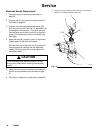
Use the megohmmeter (A), part no. 218979, and an
applied voltage of 500 volts to complete these
electrical tests. Connect the leads as shown.
Test Gun Resistance
NOTE: The fluid passage must be flushed and dried
to get an accurate reading. Check the resistance with
the gun triggered and untriggered.
1. Prepare the gun for service as instructed on
page 30.
2. Measure the resistance between the end of the
gun electrode (20) and the air inlet fitting (17). See
Fig. 13.
3. The resistance should be between 180 to 220
megohms. If the resistance is outside the specified
range, go to the next test.
4. If you still have problems, refer to Voltage Loss
Troubleshooting, page 22, for other possible
causes of poor performance, or contact the near-
est authorized service agency.
Fig. 13
17
20
A
KEY-Fig. 13
A Megohmmeter
17 Air Inlet Fitting
20 Electrode
5153B
Continued on the next page.