


308584 35
Service
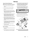
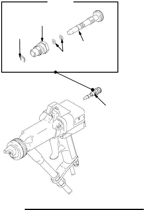
Fan Air Adjustment Valve Repair
NOTE: The fan air valve (43) can be replaced as an
assembly or as individual parts.
1. Prepare the gun for service as instructed on
page 30.
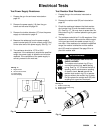
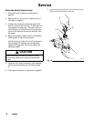
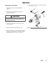
2. Place a wrench on the flats of the valve housing
and remove it from the handle. See Fig. 21.
3. If the parts are purchased separately, install them
as instructed in steps 4 to 8.
If installing the complete valve, go to step 8.
4. Remove the retaining ring (43b). Rotate the air
adjusting screw (43c) counterclockwise until it is
disengaged from the valve housing threads (43d).
Pull the adjusting screw out of the valve housing.
5. Clean all the parts and inspect them for wear or
damage.
6. Install the o-rings (43e) on the adjusting screw
(43c). Lubricate the o-rings and the adjusting
screw threads with petroleum jelly.
7. Install the adjusting screw (43c) into the valve
housing (43d), and install the retaining ring (43b)
on the adjusting screw (43c). Back the adjusting
screw out of the valve housing until it bottoms out
against the retaining ring.
8. Apply PTFE paste to the threads of the valve
housing (43d) and install it in the handle. Torque
the housing to 10 to 12 in-lb (1.1 to 1.4 NSm).
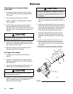
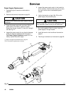
DETAIL
43
43b
43d
43e
43c
Fig. 21
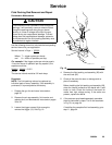
Apply a very light coat of lubricant to the o-rings (43e) and
adjusting screw (43c) threads.
Apply PTFE paste to the valve housing (43d) threads and
tighten the housing into the handle to 10–12 in-lb (1.1–1.4 NSm).
05161B
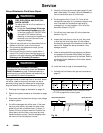
Fluid Adjustment Assembly Repair
1. Prepare the gun for service as instructed on
page 30.
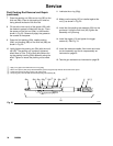
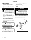
2. Using a 14 mm socket wrench, remove the fluid
adjustment assembly (45). See Fig. 22, page 36.
3. Turn the stem (45a) fully clockwise and remove
the sleeve stop (45e).
4. To completely disassemble the fluid adjustment
assembly, the sleeve stop (45e) must be
assembled back on to the stem (45a). Turn the
stem until the sleeve is protruding about 0.4 inches
(10 mm).
Continued on the next page.