


36 308584
Service
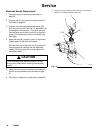
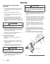
Fluid Adjustment Assembly Repair
(continued)
5. To remove the sleeve (45d), hold the cap (45c)
and turn the sleeve stop (45e) counterclockwise
with a pliers.
6. Remove the stem (45a) and o-ring (45b).
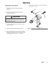
7. Repair or replace any damaged parts. Lubricate
the o-ring (45b).
8. Carefully apply low strength (purple) Loctiter or
equivalent thread sealant to the sleeve (45d)
external threads. Turn the sleeve in with the sleeve
stop (45e) until it is bottomed out, then back it out
1/8 turn.
CAUTION
Do not allow Loctite to get onto the stem (45a) during
assembly or the stem will not turn.
9. Place the fluid adjustment assembly on the work-
bench with its threaded end facing down and allow
the Loctite to cure over night.
10. After the Loctite has cured, assemble the fluid
adjustment assembly into the gun.
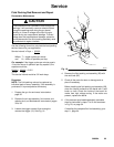
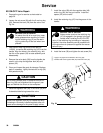
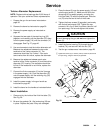
Air Trigger Valve Repair
1. Prepare the gun for service as instructed on
page 30.
2. Using a 14 mm socket wrench, remove the fluid
adjustment assembly (45), o-ring (23), and spring
(44). See Fig. 22.
3. Loosen the air valve packing nut (40) one full turn.
Remove the air valve shaft (39) with a pliers.
CAUTION
When removing the air valve shaft (39), be careful
not to damage the seat area.
4. Check the o-rings (41, 23) for damage and replace
them if necessary. Apply a very light coat of
petroleum jelly to the o-rings.
CAUTION
Do not over-lubricate parts. Excessive lubricant on
the o-ring (41) and air valve shaft (39) can be pushed
into the gun air passage and blemish the finish on
the workpiece.
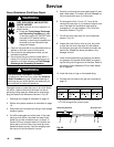
5. Unscrew the packing nut (40) to check the u-cup
(42). Do not remove the u-cup unless it is dam-
aged.
6. Install the air valve shaft (39), with the o-ring (41),
and spring (44) into the back of the gun handle (7).
If the u-cup (42) was removed, install the air valve
shaft (39) before installing the u-cup. Install the
u-cup with its lips facing into the gun handle.
7. Install the fluid adjustment knob (45), with the
o-ring (23). Tighten the cap with a screw driver.
Tighten the air valve packing nut (40) until it bot-
toms.
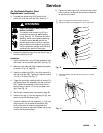
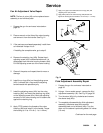
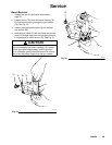
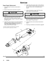
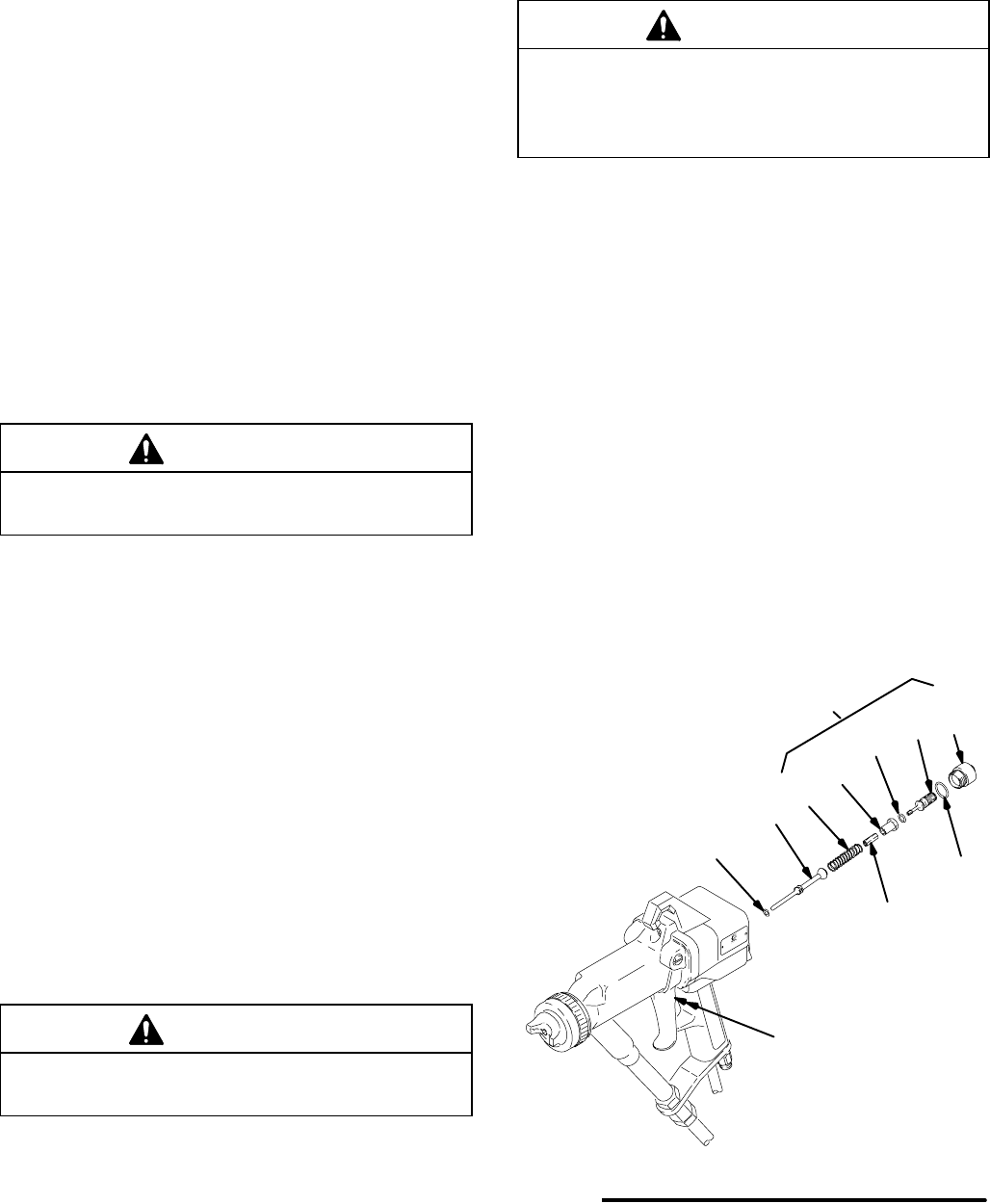
Fig. 22
41
39
44
23
45a
40, 42
45e
45d
45b
45c
45
Apply a very light coat of lubricant to the o-rings (41, 23).
Carefully apply low strength (purple) Loctite or equivalent to
sleeve (45d) external thread. Turn sleeve in with sleeve stop
(45e) until it bottoms out, then back out 1/8 turn. Allow Loctite to
cure overnight.
Do not remove u-cup (42) unless damaged. Install with lips
facing into handle. Tighten packing nut (40) until it bottoms.
05162B