


308584 41
Service
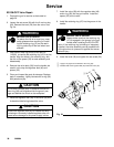
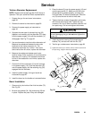
Turbine Alternator Replacement
NOTE: Replace turbine bearings after 2,000 hours of
operation. See your authorized Graco representative.
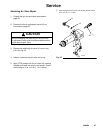
1. Prepare the gun for service as instructed on
page 30.
2. Remove the barrel as instructed on page 39.
3. Remove the power supply as instructed on
page 40.
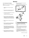
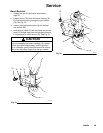
4. Squeeze the two ends of the retaining ring (35)
together, and carefully pull the alternator (37) away
from the power supply (18) until the connector (V)
disengages. See Fig. 27, page 40.
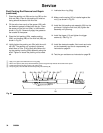
5. Use an ohmmeter to test the turbine alternator coil.
Measure the resistance between the two outer
terminals of the 3-wire connector (V). The
resistance should be 3 to 5 ohms. If the resis-
tance varies from this value, replace the alternator.
6. Measure the resistance between each outer
terminal of the 3-wire connector (V) and the turbine
alternator (37) housing. The resistance should be
infinite. If the resistance is not infinite, replace the
alternator.
7. Connect the 3-wire connector (V) to the 3 prongs
in the power supply (18). Push the alternator (37)
onto the power supply until the retaining ring (35)
engages with the alternator.
8. Install the power supply in the gun handle as
instructed on page 40.
9. Install the barrel on the handle as instructed below.
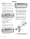
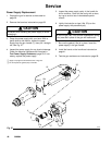
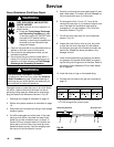
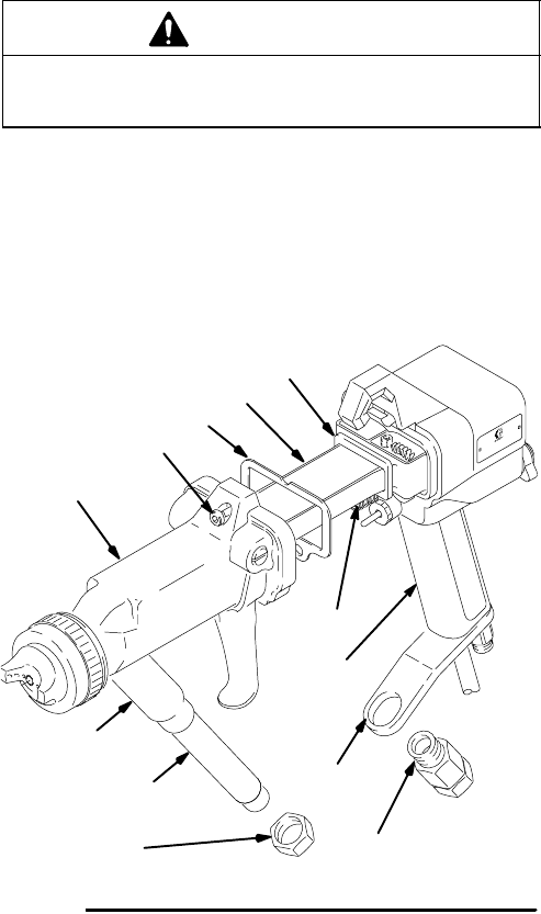
Barrel Installation
1. Clean and dry the inside of the fluid inlet tube (75).
See Fig. 28.
2. Be sure the gaskets (34, 18a) and spring (30) are
in place. Replace the parts if they are damaged.
3. Place the barrel (3) over the power supply (18) and
onto the gun handle (7). Make sure the fluid nee-
dle spring (30) is seated properly, and align the
fluid inlet tube (75) with the bracket port. Slide the
nut (78) onto the end of the fluid inlet tube.
4. Tighten the three screws (5) oppositely and evenly
with the ball-end wrench (63). Tighten the cap
screws to 18 in-lbs (2 NSm) maximum (about a half
turn past snug). Do not over-tighten the screws.
CAUTION
To avoid damaging the gun, do not over-tighten the
screws (5).
5. Install the ferrule housing (79) through the gun
bracket (76), and secure it with the nut (78).
6. Test the gun resistance as instructed on page 28.
Fig. 28
18a
18
34
5
3
30
7
75
78
79
76
Tighten the screws (5) to 18 in-lbs (2 NSm) maximum (about half
turn past snug), using the wrench (63) provided..
91
05158B