-2-
G1970/G1971/G1972 Pneumatic Sanding Drum
Operation
1. DISCONNECT BUFFER FROM POWER!
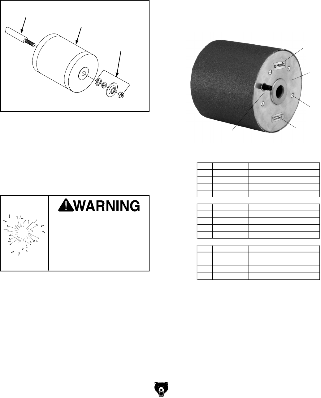
2. Install the sanding drum on the buffer shaft
using the spacers and flanges included with
the buffer (Figure 2
).
3. Slide the sanding sleeve over the sanding
drum.
4. Use a bicycle pump (or other manual pump)
to inflate the drum until the sanding sleeve is
secure. Do not exceed the 10 PSI maximum
rating.
Figure 2. Mounting drum to shaft.
Operation Tips
• Adjust the pressure in the drum to fine-tune
its firmness for sanding contours.
• Always hold the workpiece firmly—the soft
surface of the drum will exert more force
on the workpiece than a traditional sanding
drum.
• Deflate the drum when not in use.
Buffer Shaft
Sanding Drum
Buffer Mounting
Hardware
Parts Breakdown & List
MODEL REF PART # DESCRIPTION
G1970
1 P1970001 RUBBER DRUM 3"
2 P1970002 VALVE STEM
3 PFH08 FLAT HD SCR 10-24 X 1/2
4 P1970004 10 PSI MAX. LABEL
5 P1970005
AIR COMPRESSOR LABEL
G1971
1 P1971001 RUBBER DRUM 4"
2 P1971002 VALVE STEM
3 PFH08 FLAT HD SCR 10-24 X 1/2
4 P1970004 10 PSI MAX. LABEL
5 P1970005
AIR COMPRESSOR LABEL
G1972
1 P1972001 RUBBER DRUM 6"
2 P1972002 VALVE STEM
3 PFH08 FLAT HD SCR 10-24 X 1/2
4 P1970004 10 PSI MAX. LABEL
5 P1970005
AIR COMPRESSOR LABEL
If you need help with your new pneumatic tool,
call our Tech Support at: (570) 546-9663.
Replacement Sanding Sleeves
G1973 3" x 6" x 100 Grit Silicon Carbide
G1974
3" x 6" x 150 Grit Silicon Carbide
G1975
4" x 6" x 100 Grit Silicon Carbide
G1976
4" x 6" x 150 Grit Silicon Carbide
G1977
6" x 6" x 100 Grit Silicon Carbide
G1978
6" x 6" x 150 Grit Silicon Carbide
4
EXPLOSION HAZARD!
Do not use an air compressor
to inflate the sanding drum!
Over-inflation will cause the
bladder to explode, resulting
in personal injury and/or tool
damage
1
2
3
5


