


-19-
G8030 3 H.P. Overarm Router
Cutting Depth
Control Knob
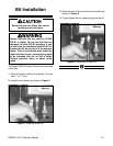
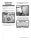
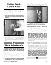
The Model G8030 uses a rapid adjusting ring to
control the cutting depth of the spindle. There are
six settings on the ring.
1. Simply twist the ring to the adjustment that cor-
responds with the depth required as shown in
Figure 19.
2. Each number has a corresponding bolt that
can be adjusted to a predetermined depth.
This will be explained further in the next sec-
tion.
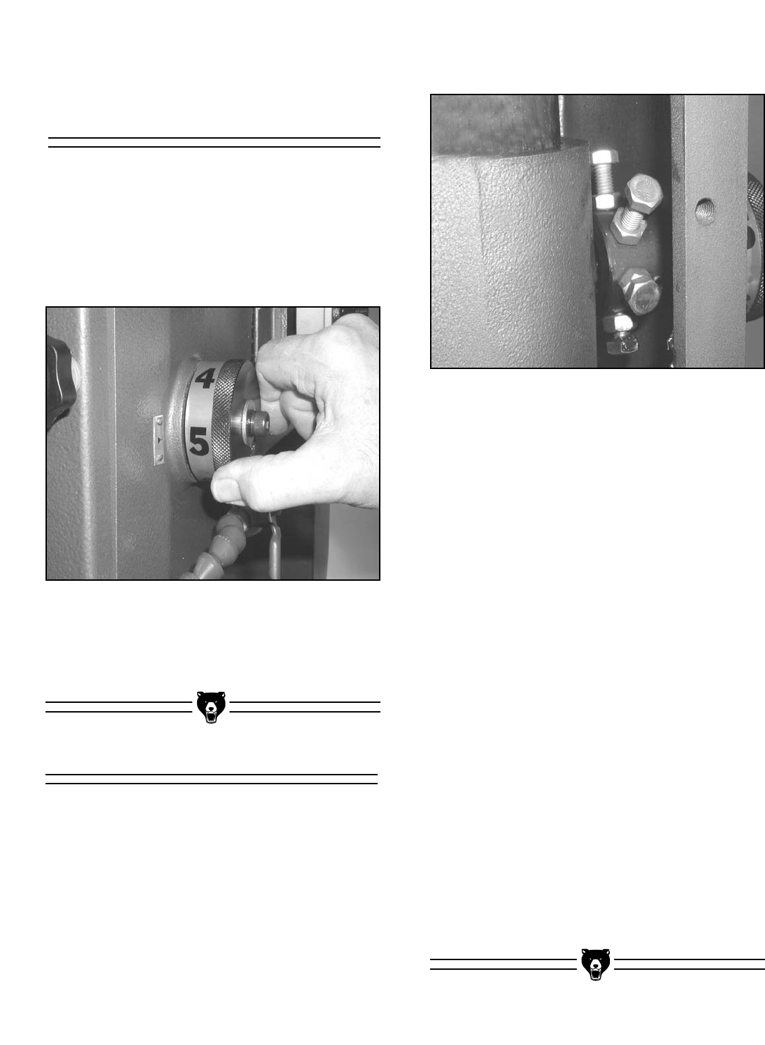
Micro Adjustments
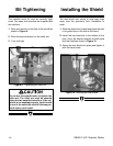
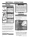
3. Back off the locking nut a quarter turn. Then
adjust the bolt as shown in Figure 20.
The Model G8030 spindle depth stop can be fine-
ly adjusted from the bolts on the inside of the
head cover, which are fixed to the depth control
wheel.
1. Open the door on the front of the head and
locate the bolts. Note that there are locking
nuts on each adjustment bolt.
2. The indicated number on the depth control ring
corresponds to the bolt in the vertical position.
4. Retighten locking nuts and check settings.
5. Bolt heads can be reached in sequence by
turning the depth control ring.
6. You will need to make sure the cutting bit
doesn’t slam into the table when the foot pedal
is pressed. Measure the distance between the
end of the installed bit and the table. This dis-
tance should always be greater than the dis-
tance between the depth setting bolt head and
the stationary hex bolt head immediately
above the depth setting bolt head. This will
ensure the bit will not hit the table. The next
step will be to fine tune the depth for the spe-
cific application.
7. Place the desired workpiece onto the router
table. If a template tray/pattern is used under
the workpiece, make sure that it is in place.
Now measure the distance between the bot-
tom of the cutting bit and the top surface of the
workpiece. Add this measurement to the depth
of cut you want to make. This is the overall dis-
tance that the bit should plunge. Make sure
that the distance between the hex bolt head on
the depth setting ring, and the one directly
above it, is the same as the overall distance
you want the bit to plunge. Test the setup on a
piece of scrap wood of the same thickness.
Figure 20. Locking bolts and lock nuts.
Figure 19. Depth control ring.