


!
-21-
G8030 3 H.P. Overarm Router
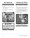
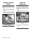
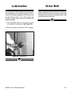
Figure 22. Location of guide pin height lock.
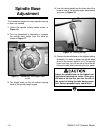
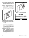
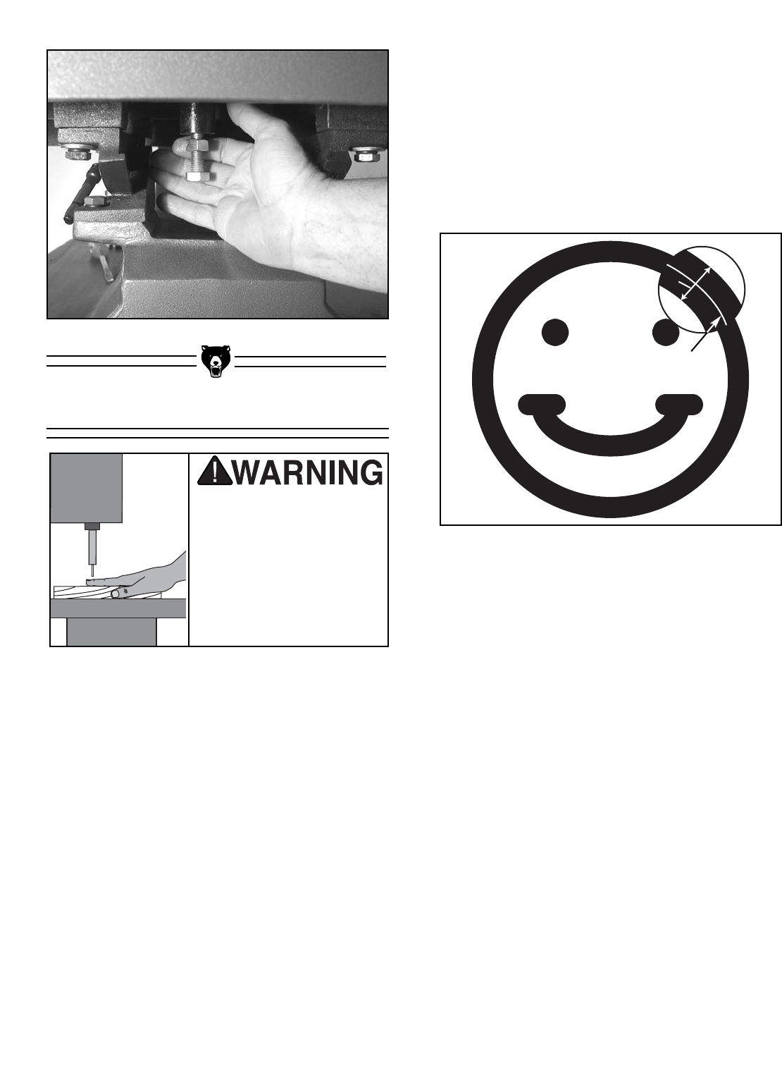
Figure 23. “X” equals the diameter of the router
bit.
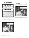
Pattern Routing
The overarm pin router truly excels in the area of
pattern routing. The basic set-up consists of a
guide pin and router bit that have the same diam-
eter. The guide pin is mounted in the table direct-
ly below the position of the installed router bit.
When used in conjunction with a pattern mounted
to the underside of the workpiece, the operator is
able to guide the pattern along the pin while trans-
ferring the exact routing path to the top of the
workpiece.
This operation can be used to rout consistent
grooves in the tops of workpieces; however, it can
also be used to cut consistent shapes completely
out of workpieces. It is also helpful when many
pieces of the exact same profile are required, or
when making even one cutting operation where
absolute precision is required on the initial
attempt. It only takes one mistake to ruin expen-
sive lumber or a time consuming assembly.
The key to successful pattern routing is having
good patterns to follow. The time you spend mak-
ing accurate patterns will save a lot of time during
production runs, as well as reducing the amount
of wasted lumber from mis-cuts. Take the time to
follow our pattern making directions and you will
be on your way to very efficient routing opera-
tions. For this example, we will be making a “smi-
ley” face.
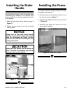
1. Draw out the full scale pattern on a piece of
paper. A computer aided drawing program
can be helpful here, but it is not necessary. Be
sure that the pattern drawing takes into
account the area that will be cut away during
the routing operation. It is best to draw a line
that represents the centerline, then draw two
more lines on each side of the centerline, rep-
resenting the actual width of the routed line.
For example, we are using a
1
⁄4" bit, so we
need to measure
1
⁄8" off of either side of the
centerline to account for the full width of the
routed line as shown in Figure 23.
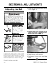
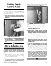
2. Using spray adhesive, glue the paper pattern
to a piece of
1
⁄8" to
1
⁄4" birch plywood.
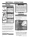
3. Using a jig saw or scroll saw, cut out the area
that represents the full width of the routed
area. Use a drill to make saw starts that are
located on the inner part of the pattern. A
1
⁄4"
diameter drill bit can also be used to make the
rounded holes and ends of lines.
Make sure that your
hands and fingers are
not in the path of the
router bit before acti-
vating the foot pedal.
Failure to do so could
result in serious per-
sonal injury.
X
Centerline