


SKU 95668 For technical questions, please call 1-800-444-3353 PAGE 11
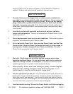
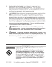
FIGURE H
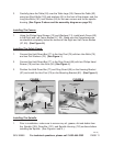
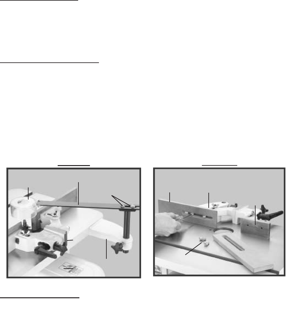
RIGHT FENCE BODY
(not Shown)
(57)
LEFT FENCE BODY
(59)
FENCE
(60)
PHILIPS HEAD SCREWS (12)
WASHERS (13)
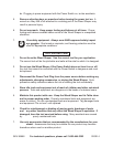
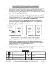
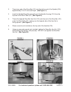
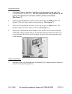
Installing The Safety Guard:
1. Connect the Hold Down Bar (77) to the Hex Post (79) with two Hex Bolts (75)
and two Flat Washers (76). (See Figure I.)
2. Connect the Hold Down Bar (77) to the Ring Guard (85) with two Philips Head
Screws (78) and two Hex Nuts (84) (See Figure I.)
3. Position the Hold Down Bar (77) and Ring Guard (85) on the Housing Bracket
(87) and install the Hex Post (79) on the Mounting Bracket (82). (See Figure I.)
FIGURE I
HOLD DOWN BAR
(77)
RING GUARD
(85)
MOUNTING BRACKET
(82)
HOUSING
BRACKET
(87)
PHILIPS HEAD SCREWS (78)
HEX NUTS (84)
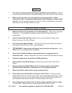
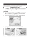
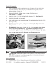
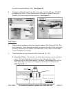
Installing The Spindle:
Prior to installation, make sure to remove any oil, grease, dirt and debris from 1.
the Spindle (105), Draw Bar (121), and Spindle Housing (110) surfaces before
installing the Spindle. (See Figures J and K.)
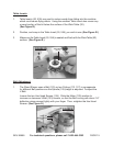
1. Using the Philips Head Screws (12) and Washers (13), install each Fence (60)
to the Right and Left Fence Bodies (57, 59). Make sure the Screwheads are
countersunk completely below the surface of the Right and Left Fence Bodies
(57, 59). (See Figure H.)
Installing The Fences:
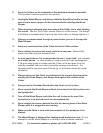
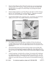
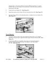
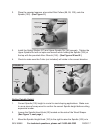
Carefully place the Table (52) over the Table Legs (28). Secure the Table (52) 3.
using two Short Bolts (152) and washers (65) in the front of the shaper, and ve
Long Hex Bolts (151) and Washer (65) for the rear corners and for the spindle
housing. (See Figure G above and the assembly diagram on page 29.)
REV 07j