


Twin Halogen Light
Model SL-5592
© 2007 HeathCo LLC 595-5690-04
1. For easy installation, select an existing light that is operated by
a wall switch for replacement.
Wiring and Final Assembly
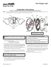
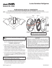
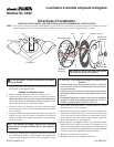
2. Put the gasket in place before connecting wires.
3.
Connect the fixture wires to the junction box wires (black to black,
white to white, and junction box ground wire to green ground
screw on fixture.). Secure with wire connectors provided.
4. Make sure the wire connectors and wires are inside the junction
box. Secure the fixture with the screws provided.
5. If not installed on a weatherproof box or if an adaptor plate was
used, caulk the wall plate and mounting surface with silicone
weather sealant.
Installation Instructions
READ ALL INSTRUCTIONS CAREFULLY BEFORE BEGINNING INSTALLATION.
NOTE: All wiring must be run in accordance with the National Electrical Code through conduit or another acceptable means. Contact
a qualified electrician if there is any question as to the suitability of the system.
7. To adjust shields, loosen set screws (
C) and turn shield coun-
terclockwise about 1/3 turn and remove shield. Reinstall shield
and turn clockwise to desired position. Tighten set screw (C).
8. To replace lamps, remove shields as above. Line up lamp pins with
lamp socket holes. Carefully push lamps straight in. Lamps are quite
fragile and can be easily broken if side pressure is applied.
9. Replace lamp shields.
10. Turn on the circuit breaker and light switch.
Junction Box
Gasket
CAUTION to avoid fire or burn hazards:
• Allow fixture to cool before touching. The bulbs and fixture
operate at high temperatures.
• Keep fixture at least 2" from combustible materials. Do
not aim at objects closer than 3 feet.
• Re-lamp with T4 100W (max.) G8 type halogen bi-pin 120
VAC lamps only. Use Heath
®
/Zenith P/N SL-5591-A2.
Black White(A)
(B)
Shields
(C)
Rubber
Plug
Junction box ground wire to
green ground screw on fixture.
Mounting Strap
Mounting
Bolt
WARNING: Turn power off at the circuit breaker or
fuse.
NOTICE: Lamp holders must be aimed downward a
minimum of 30° below horizontal.
6. Adjust the lamp holders by loosening the lock nuts (A) and/or
lock screws (B) but do not rotate the lamp holders more than
180˚ from the factory setting. Tighten the lock nuts and lock
screws after adjusting the fixture.