


H.E.R.O. INDUSTRIES 1100C & 1100NC OWNERS MANUAL
12
pump is known as the paint or material pump. The paint system is made up of two basic valves, the paint
intake valve assembly (ref# 16-28), paint outgo valve, (ref# 32). For correct operation, all four valves must
be in good working condition. For this manual we will refer to the two systems as "hydraulic" and "paint".
At the center of these two pumps is the diaphragm. The diaphragm is a flexible nylon disc which transfers
the energy (pressure) created by the hydraulic pump, to create energy (pressure) in the paint pump. The
function of the diaphragm is to create a barrier between the hydraulic oil and the spray material and transfer
the energy created.
To fully understand and trouble shoot a H.E.R.O. pump, always keep in mind that "for every action,
there is an opposite or corresponding re-action". For every action of the hydraulic intake valve (ref# 59),
there is an opposite re-action of the hydraulic outgo valve (ref# 70). At the same time there are
corresponding re-actions taking place within the paint pump. This means that as the hydraulic intake valve is
opening, so is the corresponding paint intake valve, and while the hydraulic outgo valve is closing, so is the
corresponding paint outgo valve. The operation and function of each valve is discussed at the end of this
section.
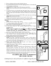
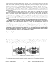
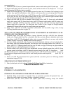
For correct operation to begin, the hydraulic system must be fully primed and all air must be removed
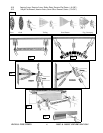
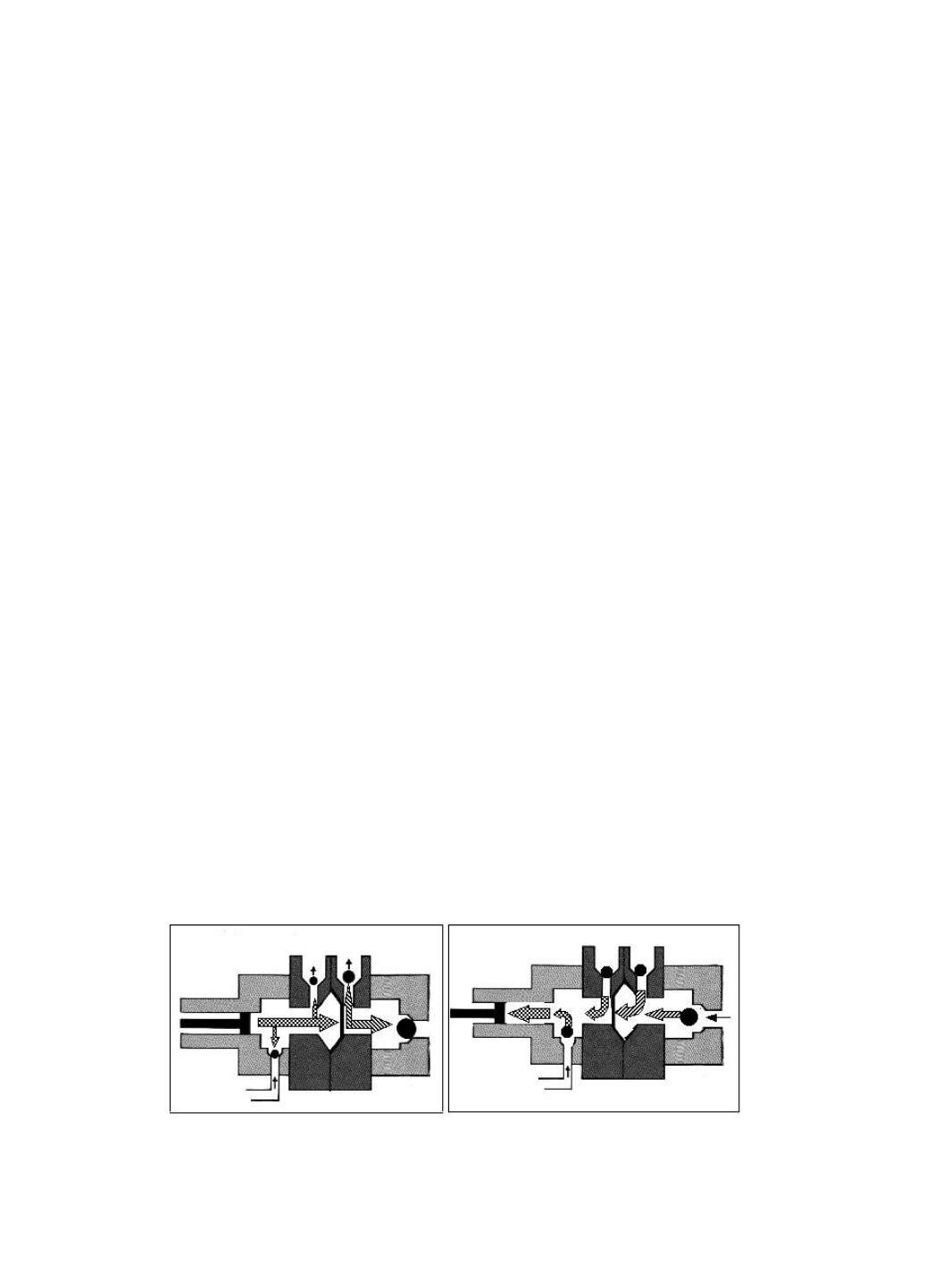
( see "purging" page 16 ). Operation begins with piston in the backward position (fig.# 2). At this point the
hydraulic intake is open, while the hydraulic outgo valve is closed. The corresponding paint valves are in
similar positions.
As the piston moves forward, it pushes hydraulic oil forward. This movement of oil causes the hydraulic
intake valve to close and the diaphragm to move forward (fig.# 1). The hydraulic outgo valve will remain
closed until sufficient pressure is created to cause it to open. While the hydraulic valves are operating a
corresponding re-action is taking place in the paint valves. The forward movement of the diaphragm pushes
the paint, causing the paint intake valve, (ref# 16-28) to close. The trapped paint requires a means of release,
so it forces the outgo valve, (ref# 32), to open and paint flows to the gun.
Fig. 1 Fig. 2
The backward movement of the piston, creates a vacuum in the hydraulic system. This causes the hydraulic
outgo valve to close and the hydraulic intake valve to open (fig# 1). Opening of the hydraulic intake valve
allows a new supply of hydraulic oil to enter the system, replacing the oil which was used on the forward
stroke. Once again a corresponding re-action is taking place in the paint pump.
TROUBLESHOOTING
The diaphragm is being pushed backward by the intake spring, (ref# 48). The backward diaphragm