


H.E.R.O. INDUSTRIES 1100C & 1100NC OWNERS MANUAL
13
movement causes a vacuum in the paint pump. This vacuum causes the intake valve to open, allowing a new
supply of paint to enter. The corresponding paint outgo valve is drawn closed by the vacuum created by the
diaphragm.
These operations are repeated at a rate of 750 times a minute. These continuously repeated actions draw
paint into the pump, pressurize it, and then deliver it to the gun. The failure, of any one valve, to operate
correctly will effect the overall equipment performance.
Each of the four valves mentioned earlier, have an important function and will effect the overall
performance of the unit if not performing correctly.
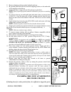
HYDRAULIC INTAKE VALVE (REF# 59, PART # 4-30)
The hydraulic intake valve, is a small vacuum valve which controls the hydraulic oil entering the
hydraulic pump/cylinder area. Once the oil has past through the valve it is prevented from returning. The
valve is commonly called a “one way check valve”. Valve failure will result in the hydraulic pump being
unable to build pressure, and the diaphragm will stop moving. Spray pressure will cease.
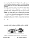
HYDRAULIC OUTGO VALVE (REF# 70, PART# 4-27C)
The hydraulic outgo valve, better known as the "pressure control valve", is used to control the units
operating pressure. The valve is fully adjustable from 0 psi. to 3000 psi. By turning the pressure control valve
knob (ref# 71) clockwise the pressure is increased. The hydraulic pump continues to build at all times and
must have a means of releasing this pressure. Pressure applied to the P.C. ball, (ref# 84) will keep it lodged
in the P.C. seat (ref# 83) until the internal hydraulic oil pressure is sufficient to cause it to open. The point at
which the oil is released is equal to the level set by the control knob. As components within the pressure
control valve wear, the valve looses its ability to maintain or reach the required pressures (see "low static
pressure").
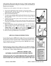
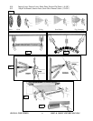
PAINT INTAKE VALVE ASSEMBLY (REF# 16-28)
The paint intake valve is made up of seven (7) items, endcap and seat (ref# 16 & 17), intake ball (ref# 18),
cage (ref# 19) spring (ref# 20), O-ring (ref# 21), material head (ref# 22). The intake valve controls the
incoming flow of spray materials and is responsible for keeping them from returning to the source. The ball
must be able to create a complete seal on the seat, otherwise pressure will be lost. A worn intake valve may /
will permit correct static pressure, but supply lower spray pressure. A worn intake ball will become smaller
in diameter and loose its ability to seal at the seat. A worn seat will develop a large step in the area where
contact with the ball is made. This can cause the intake ball to distort in shape making the ball egg shaped. If
the valve assembly becomes warm to the touch, this may be a sign of a loose or worn seat caused by wear or
washout / erosion. The intake seat is Lock-Tited into the endcap block. Over time the seat may become loose
due to erosion of the metal. Replacement of a worn seat (ref# 17) is possible, see page 21. Replacement of
the endcap, complete with seat is required if any signs of erosion is evident upon inspection.
PAINT OUTGO VALVE (REF# 32, PART# 4-11A)
The paint outgo valve monitors and controls the flow of spray materials as it leaves the sprayer. It also works
together with the paint intake valve, to build paint pressure as specified by the setting made by the hydraulic
outgo valve (pressure control valve). A worn outgo valve will result in pulsation in the spray material and
cause the paint hose to jump and vibrate vigorously.
TROUBLESHOOTING
The solution to almost all problems can usually be found in the paint side valves. However, before
performing any repair or looking further, the following are things which can cause an apparent sprayer
failure, without any mechanical problem. ALWAYS check these items before preceding.