


GLOSSARY OF TERMS
– 10 –
English
DRILL PRESS TERMS
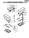
BASE GUIDES – Supports drill press. For additional stability,
holes are provided in base to bolt drill press to bench.
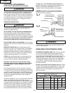
BACKUP MATERIAL – A piece of scrap wood placed
between the workpiece and table. The backup board prevents
wood in the workpiece from splintering when the drill passes
through the backside of the workpiece. It also prevents drilling
into the table top.
BELT GUARD ASSEMBLY – Covers the pulleys and belt
during operation of the drill press.
BELT TENSION – Refer to the Assembly Section, “Installing
and Tensioning Belt”.
BELT TENSION LOCK KNOBS – Tightening the knobs locks
the motor bracket support and the belt tension handle,
maintaining correct belt distance and tension.
BEVEL SCALE – Shows degree of table tilt for bevel
operations. The scale is mounted on the side of the table
bracket.
CHUCK – Holds a drill bit or other recommended accessory
to perform desired operations.
CHUCK KEY – A self-ejecting chuck key which will pop out
of the chuck when you let go of it. This action is designed to
help prevent throwing of the chuck key from the chuck when
the power is turned ON. Do not use any other key as a
substitute; order a new one if Damaged or Lost.
COLUMN – Connects the head, table, and base on a one
piece tube for easy alignment and movement.
COLUMN COLLAR – Holds the rack to the column. The rack
remains movable in the collar to permit table support
movements.
COLUMN SUPPORT – Supports the column, guides the rack
and provides mounting holes for the column to the base.
DEPTH SCALE STOP NUTS – Lock the spindle to a
selected depth.
DEPTH SCALE – Indicates depth of hole being drilled.
DRILL BIT – The cutting tool used in the drill press to make
holes in a workpiece.
DRILL ON/OFF SWITCH – Has a locking feature. This
feature is intended to help prevent unauthorized and possible
hazardous use by children and others. Insert the key into the
switch to turn the drill press on.
DRILLING SPEED – Changed by placing the belt in any of
the steps (grooves) in the pulleys. See the Spindle Speed
Chart inside belt guard or in the manual.
FEED HANDLE – Moves the chuck up or down. If necessary,
one or two of the handles may be removed whenever the
workpiece is of such unusual shape that it interferes with the
handles.
RACK – Combines with gear mechanism to provide easy
elevation of the table by the hand operated table crank.
RPM – Revolutions per minute. The number of turns
completed by a spinning object in one minute.
SPINDLE SPEED – The RPM of the spindle.
SPRING CAP – Adjusts the quill return spring tension.
TABLE SUPPORT LOCK – Tightening locks the table
support tot he column. Always have it locked in place while
operating the drill press.
TABLE – Provides a working surface to support the
workpiece.
TABLE ARM – Extends beyond the table support for
mounting and aligning the table.
TABLE BEVEL LOCK – Locks the table in any position from
0° to 45°.
TABLE CRANK – Elevates and lowers the table. Turn
clockwise to elevate the table. Support lock must be released
before operating the crank.
TABLE LOCK – Locks the table after it is rotated to various
positions.
TABLE SUPPORT – Rides on the column to support the
table arm and table.
WORKPIECE – Material being drilled.