


DRILL PRESS ADJUSTMENTS
CAUTION: All the adjustments for the operation of the drill
press have been completed at the factory. Due to normal
wear and use, some occasional readjustments may be
necessary.
To prevent personal injury, always disconnect the plug from
the power source when making any adjustment.
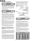
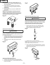
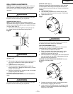
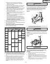
TILTING THE TABLE (Fig. H)
NOTE: The bevel scale has been included to measure
approximate bevel angles. if precision is necessary, a square
or other measuring tool should be used to position the table.
To use the bevel scale (1):
1. Remove pin and nut (2). Tighten nut until pin slips out.
2. Loosen the large hex head bevel locking bolt (3).
To prevent injury, be sure to hold the table assembly, so it will
not swivel or tilt.
3. Tilt the table, aligning the desired angle measurement to
the zero line scribed on the table opposite the bevel
scale (1).
4. Tighten the bevel locking bolt (3).
5. To return the table to its original position, loosen the
bevel locking bolt (3). Realign the bevel scale (1) to the 0
scribed line on the table.
6. Back nut out several turns, reinsert pin and nut into table,
and tap into place with hammer.
7. Tighten the bevel locking bolt.
NOTE: The table has been removed from the illustration for
clarity.
To prevent personal injury, always disconnect the plug from
the power source when making any adjustment.
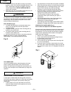
SPINDLE / QUILL (Fig. I)
Rotate the feed handles counterclockwise to lower spindle to
its lowest position. Hand support the spindle securely and
move it back and forth around the axis. If there is play, do the
following:
1. Loosen the lock nut (1).
2. Turn the screw (2) clockwise to eliminate the play, but
without obstructing the upward movement of the spindle.
3. Tighten the lock nut (1).
To prevent personal injury, always disconnect the plug from
the power source when making any adjustment.
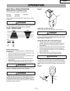
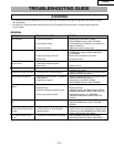
QUILL RETURN SPRING (Fig. J)
The quill return spring may need adjustment if the tension
causes the quill to return too rapidly or too slowly.
1. Lower the table for additional clearance.
2. Place a screwdriver in the lower front notch (1) of the
spring cap (2). Hold it in place while loosening and
removing only the outer jam nut (3).
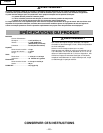
3. With the screwdriver still engaged in the notch loosen the
inner nut (4) just until the notch (5) disengages from the
boss (6) on the drill press head.
CAUTION: DO NOT REMOVE THIS INNER NUT, because
the spring will forcibly unwind.
4. Carefully turn the spring cap (2) counterclockwise with
the screwdriver, engaging the next notch.
5. Lower the quill to the lowest position by rotating the feed
handle in a counterclockwise direction while holding the
spring cap (2) in position.
WARNING
WARNING
WARNING
WARNING
Fig. H
2
1
3
Fig. I
1
Fig. J
1
2
3
4
5
6
2
– 13 –
English