


English
14
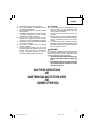
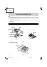
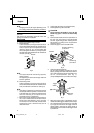
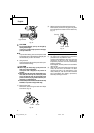
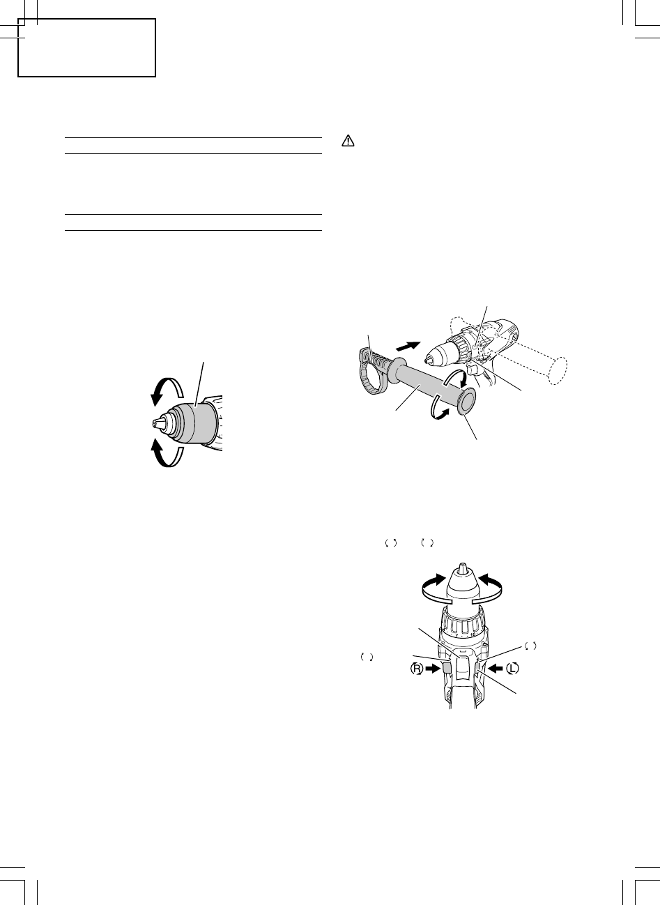
Tighten
Loosen
Sleeve
Fig. 5
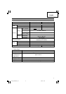
NOTE:
Charging times may be longer depending on the
surrounding temperature and battery conditions.
BEFORE USE
Check the work area to make sure that it is clear of debris
and clutter.
Clear the area of unnecessary personnel. Ensure that
lighting and ventilation is adequate.
OPERATION
1. Mounting and dismounting of the bit.
(1) Mounting the bit.
Loosen the sleeve by turning it toward the left (in
the counterclockwise direction as viewed from the
front) to open the clip on the keyless chuck. After
inserting a driver bit, etc., into the keyless drill
chuck, and tighten the sleeve by turning it toward
the right (in the clockwise direction as viewed from
the front). (See Fig. 5).
NOTE:
If the sleeve becomes loose during operation,
tighten it further.
The tightening force becomes stronger when the
sleeve is tightened.
(2) Dismounting the bit
Loosen the sleeve by turning it toward the left (in
the counterclockwise direction as viewed from the
front), and then take out the bit etc. (See Fig. 5)
NOTE:
⅜
If the sleeve is tightened in a state where the clip
of the keyless chuck is opened to a maximum limit,
a click noise may occur. This is the noise that occurs
when the loosening of the keyless chuck is
prevented and is not a malfunction.
⅜
When it is no longer possible to loosen the sleeve,
use a vise or similar instrument to secure the bit.
Set the clutch mode between 1 and 11 and then
turn the sleeve to the loose side (left side) while
operating the clutch. It should be easy now to
loosen the sleeve.
2. Confirm that the battery is mounted correctly.
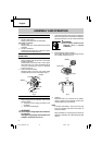
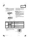
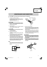
3. Installing/Removing the side handle.
CAUTION
Firmly install the side handle. If loose, the side
handle may gyrate or fall out and cause bodily
injury.
(1) Install the side handle so that the protrusions on
the main unit and grooves on the side handle
interlock. Tighten the grip after checking that the
side handle is not riding on the slip prevention
protrusion. (Fig. 6).
(2) Loosen the grip to remove the side handle.
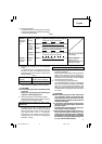
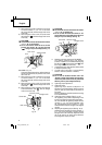
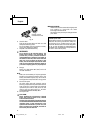
4. Check the rotational direction.
The bit rotates clockwise (viewed from the rear
side) by pushing the R-side of the selector button.
The L-side of the selector button is pushed to turn
the bit counterclockwise (See Fig. 7).
(The
L
and
R
marks are provided on the body.)
⅜
When the trigger switch is depressed, the tool
rotates. When the trigger is released, the tool stops.
⅜
The rotational speed of the drill can be controlled
by varying the amount that the trigger switch is
pulled. Speed is low when the trigger switch is
pulled slightly and increases as the trigger switch
is pulled more.
Fig. 7
Fig. 6
R
marks
L
marks
Trigger
switch
Selector
button
Tighten
Loosen
Concave
Side handle
Rotate preventing
protrusion
Slip
preventing
protrusion
Grip
01Eng_DS18DSDL_US1 1/24/12, 16:1414