IND.CONT.EQ.
3JHX
INSTALLATION INSTRUCTIONS
62-0245—01
Solid Core and Split Core 4-20 mA
Output Current Sensors
CTS-20; CTP-20
SAFETY
For CTS-20 Series current sensors, ensure
that all power sources are disconnected and
locked out before installation as severe injury
or death may result from electrical shock due
to contact with high voltage wires.
This product is not intended to be used for life
or safety applications.
This product is not intended for use in any
hazardous or classified locations.
INSTALLATION
Make sure that all installations are in compliance with all
national and local electrical codes. Only qualified
individuals that are familiar with codes, standards, and
proper safety procedures for high-voltage installations
should attempt installation. The current sensor is a 2-
wire, 4 to 20 mA Loop Powered device that requires a
regulated +12 to 30 Vdc external power source.
IMPORTANT
The current switch should be used on insulated
conductors only!
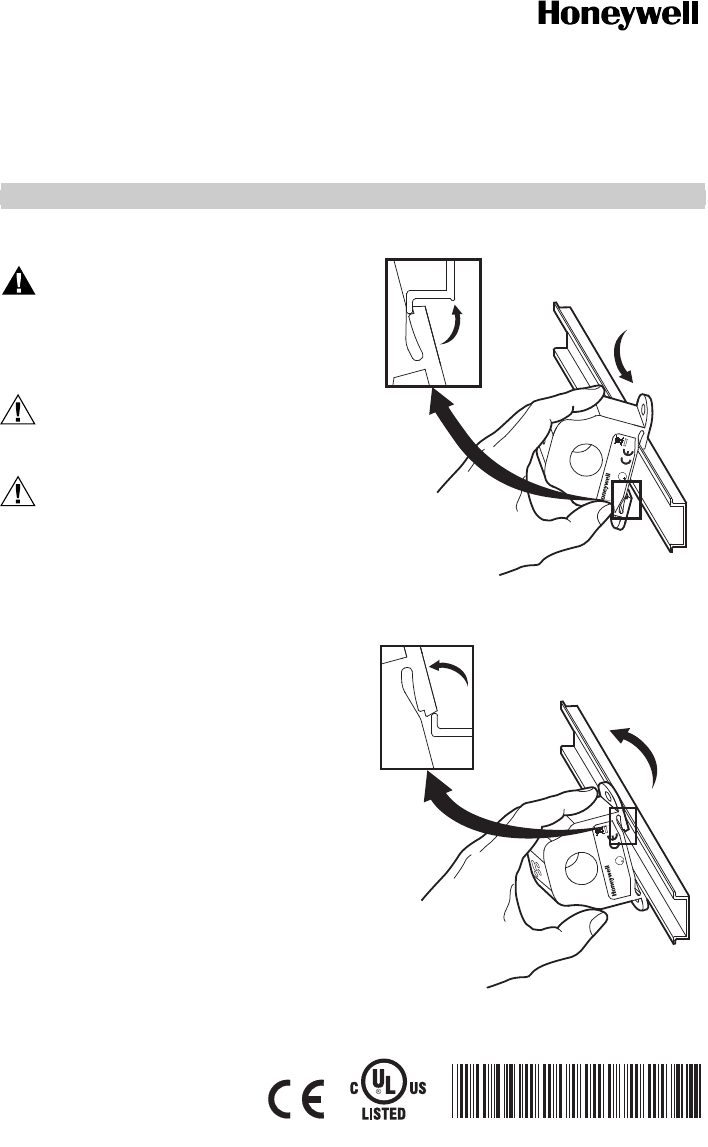
The current sensors may be mounted in any position
using the two (2) #8 x 3/4 in (19 mm) Tek screws and the
mounting holes in the base or snapped directly on to the
1-3/8 in. (35 mm) DIN rail (See Figures 3 and 4). Leave a
minimum distance of 1 in. (25 mm) between the current
sensor and any other magnetic devices such as
contactors and transformers.
Fig. 1. Sensor placed on DIN rail
Fig. 2. Sensor removed from DIN rail
C
R
U
L
U
S
3X
M25289
3X
M25290
C
R
U
L
U
S


