T7022A
Remote Temperature Sensor
INSTALLATION INSTRUCTIONS
APPLICATION
The T7022 Remote Temperature Sensor is a non-
adjustable thermistor sensor. Its primary use is with the
T7300 Programmable Commercial Thermostat (only in
return air) to control heating or cooling equipment.
NOTE: The T7022 can also be used with a T7100F,
provided the proper Q7100 subbase√one
capable of handling more than one stage of
heat√is used.
INSTALLATION
When Installing this Product...
1. Read these instructions carefully. Failure to follow
them could damage the product or cause a
hazardous condition.
2. Check the ratings given in the instructions and on
the product to make sure the product is suitable for
your application.
3. Installer must be a trained, experienced service
technician.
4. After installation is complete, check out product
operation as provided in these instructions.
CAUTION
Erratic System Operation Hazard.
Failure to follow proper wiring practices can
introduce disruptive electrical interference
(noise).
Keep wiring at least one foot away from large
inductive loads such as motors line starters,
lighting ballasts, and large power distribution
panels.
Shielded cable is required in installations where
these guidelines cannot be met.
Ground shield only to grounded controller case.
CAUTION
Electrical Shock or Equipment Damage
Hazard.
Can shock individuals or short equipment
circuitry.
Disconnect power supply before installation.
IMPORTANT
All wiring must agree with applicable codes,
ordinances and regulations.
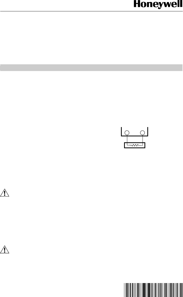
Wiring (Fig. 1)
Wiring for the T7022 Remote Temperature Sensor can
be run with class 2 wire in accordance with the National
Electrical Codes. Conduit and/or shielding are not
necessary for satisfactory operation, but conduit may be
required by local codes or practices.
T T
Q7300
T7022
M1784
Fig. 1. Typical wiring diagram.
Location
The T7022 Thermostat must be mounted in the return-air
flow in ducts (see Fig. 2 and 3) or light troffers (see Fig. 4
and 5). All mounting locations must be where the sensor
is not affected by heat from the lights or other sources.
Mounting
The T7022 can be mounted in a duct with the furnished
bracket, or in a light troffer as shown in Fig. 4 and 5 with
two rubber grommets (not supplied) if proper spacing
is available. Mounting can be directly in the return-air
passage or in an air-sampling box. The rubber grommets
can be used to wedge the sensor in slot openings of
approximately 3/8 in. to 1/2 in. wide.
When using the mounting bracket, the maximum duct
insertion length for the T7022 is approximately 2-3/4 in.
NOTE: A piece of 3/8 in. diameter conduit can be
used to extend the sensor further inside a duct
(see Fig. 3). The use of such an extension can
increase the maximum insertion length to
approximately 9-1/2 in.
® U.S. Registered Trademark
Copyright © 2001 Honeywell • All Rights Reserved
60-0247-2


