


For reels manufactured after July 1, 1999
All units are provided with right hand rotation unless otherwise
specified. This means that cable is pulled off spool top left or
bottom right (spool rotates clockwise to wind cable) when
viewing spring end of reel. See diagram on parts page.
Clock-type springs provide power for automatic cable take-up.
Spring must be pretensioned at time of installation to
insure that tension is applied to cable at all times. A tension
adjustment spanner wrench is provided with each reel.
INSTALLATION
1. Insure that machinery to be serviced by reel is at position
closest to reel.
2. Securely mount reel in desired position using 3/8"(M10)
bolts. Be sure spool is aligned with cable run.
3. Position optional cable guide, if reel is so equipped.
See CABLE INSTALLATION DRAWING.
4. Unspool cable from reel, without allowing spool to rotate, so
that desired length of cable extends from reel. Do not pull
cable directly off reel as this will apply tension to the spring
and may cause overtensioning when the reel is put into
service. Connect free end of cable to junction box on
machine or adjust cable stop
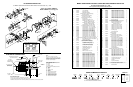
5. Remove cover plate on spring housing to expose
shaft and spring hub. (See Figure 1).
6. Insert spanner wrench into holes in spring hub (Fig 2).
Rotate wrench clockwise (for standard rotation).
Number of 360
O
turns should match last digit in model
number on serial plate.
If model number includes an “R”,
reel is reverse rotation and wrench must be rotated
counterclockwise.
(See EXPLANATION on parts list page.)
NOTE: If reel is equipped with ratcheted adjustment
wrench, follow instructions on separate sheet.
NOTE: On reels containing more than one spring, the hubs
are connected at the factory. Therefore, by tightening the
outer spring, the inside spring(s) will be tightened.
7. Remove collector cover and connect individual supply
conductors to collector terminals. See ELECTRICAL
CONNECTIONS diagram, on parts page.
CONTINUED ON BACK PAGE
INSTALLATION and MAINTENANCE INSTRUCTIONS
MMD21 GEAR DRIVE ELECTRIC CABLE REELS
MAINTENANCE
Periodically: A. Use compressed air to clean collector
assembly and inside of collector housing. Inspect collector
assembly for brush wear and pitted slip rings.
B. Inspect cable for wear
and check mounting bolts and
other hardware for tightness.
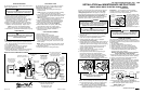
C. Check for broken springs
by pulling about 2/3 cable off
reel and observing “Broken
Spring Indicators” on sides of
spring canisters. See Fig. 3.
D. Apply grease to gears
through grease fitting on side
of gear housing.
NOTE: Bearings and springs are prelubricated and require no
periodic maintenance.
SPRING REPLACEMENT
The unique SAFETYCHANGE® spring motor consists of a
spring and hub sealed within a housing. A replacement spring
is supplied sealed in its housing and the old unit should be dis-
carded completely.
1. Turn off all electric power.
2. Disconnect cable from machine junction box.
3. Wind all cable onto reel to relieve all spring tension.
4. Remove inspection cover from face of spring housing.
5. Rotate spool clockwise and observe spring shaft. Shaft
should rotate counterclockwise and hub (with spring
attached) should remain stationary.
NOTE: Do not attempt to remove spring if resistance
is met or hub tends to rotate with shaft.
Continue to rotate spool and strike end of shaft with a rubber
mallet until shaft rotates freely and hub remains stationary.
6. Remove (4) nuts which secure spring motor(s) to frame.
7. Slide spring motor(s) off shaft and discard.
NOTE: On multi-spring reels, be sure to remove and save
dowel pins which connect one spring hub with another. Also
remove snap rings on shaft between reel housings.
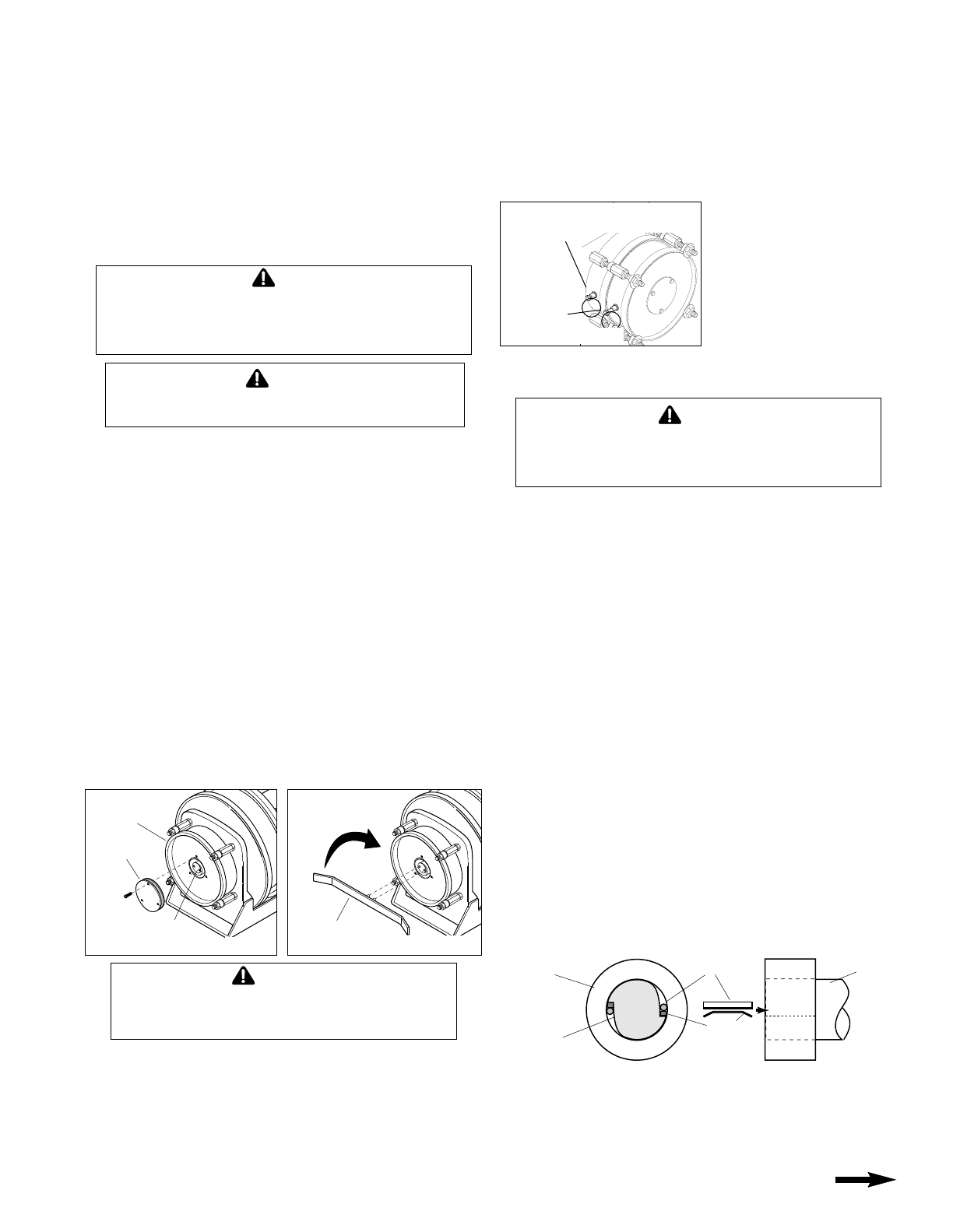
8. Install replacement spring motor(s), pawls and pawl springs.
NOTE: Pawl springs must be located between the pawls
and the deepest section of the shaft grooves. Make sure
that pawls and pawl springs are inserted flush with ends of
shaft and hub or they may rub against inspection cover.
9. Tighten nuts (and extension bolts) securing spring
housing(s) to reel frame.
10. Connect free end of cable to junction box on machine or
adjust cord stop so that desired length of cord extends from reel.
11. Tension spring with spanner wrench. Refer to
INSTALLATION section.
12. Replace inspection cover.
BROKEN SPRING
INDICATORS
“IN” with 2/3
cable off reel–
SPRING OK
“OUT” with 2/3
cable off reel–
SPRING
BROKEN
Figure 3
COVER
PLATE
SPRING
HUB
SPRING
HOUSING
CLOCKWISE
FOR STANDARD
ROTATION
SPANNER
WRENCH
Figure 1
Figure 2
PAWL
SIDE VIEW
END VIEW
SPRING
Install
against flat
SPRING
HUB
(Spring not
shown)
SHAFT
GROOVE
SPRING
SHAFT
Printed in USA
Bulletin No. 040262.c
®
HUBBELL
®
A Hubbell Company
GLEASON REEL CORP.
P.O. Box 26 • 600 South Clark St.
Mayville, WI 53050–0026
Phone 920–387–4120
Fax 920–387–4189
INSTALL CABLE
THIS DIRECTION
SLIP RING
ASSEMBLY
CABLE
SPOOL
HOOP GUIDE
PAYOFF
DIRECTION
PRETENSION
HUB
PAYOFF
DIRECTION–
OPTIONAL
GUIDE
LOCATION
POSITION CABLE
GUIDE SO THAT
ROLLER PLATE
FACES CABLE PAY-
OFF DIRECTION.
U-BOLT
WATER- TIGHT
CONNECTOR
SPRING MOTOR
SPRING
MOTOR
MAIN SHAFT
TERMINATE THIS END TO
MACHINE JUNCTION BOX
ATTACH INDIVIDUAL
CONDUCTORS TO
COLLECTOR LEADS
AT THIS END
COLLECTOR
COVER
REMOVE
LINE
ENTRANCE
(NPT)
PAYOFF
DIRECTION–
OPTIONAL
GUIDE
LOCATION
CABLE INSTALLATION REFERENCE DRAWING
SPOOL ROTATION DIRECTION
TO WIND CABLE WHEN
VIEWED FROM SPRING SIDE
(STANDARD ROTATION)
PIPE
PLUG
SPRING DETENSIONING
Use the following procedure to relieve spring tension prior to
cable or spring replacement..
1. Cycle reel thru normal operating cycle and stop when
maximum amount of cable is wound onto reel spool.
2. Set spool lock to prevent spool from turning.
3. Remove access cover from top of gearbox.
4. Using open end wrench, loosen large hex nut slowly to
allow springs to unwind. Fully loosen nut further with
wrench until springs are completely unwound.
5. Repair reel or replace springs or cable as necessary.
6. Retighten nut until definite resistance is felt and spring
washers are full compressed (flat). Replace cover.
NOTE: If hex nut is not adequately tightened,
spring unwinding can occur during reel operation.
7. Pretension reel. See INSTALLATION section, front page.
CABLE REMOVAL
Use the following procedure to remove worn or damaged cable
from reel prior to installation of new cable.
1. Move machine serviced by reel to a position closest to
reel. Springs will still be under pre-tension at this point.
2. Turn off all electric power.
3. Lock spool to prevent turning using spool lock.
4. Disconnect cable from machine junction box.
5. Detension springs as described above.
6. Remove cable from spool. Loosen U-bolt and water-tight
connector and disconnect conductors from slip ring.
CABLE INSTALLATION
Use the following procedure to replace cable or if reel was
ordered without cable. Refer to CABLE INSTALLATION
REFERENCE DRAWING, below.
1. Unspool new cable from shipping spool and lay out
to eliminate twist.
NOTE: This step is not essential, but will aid in winding
operation of the reel and prolong cable life.
2. Feed one end of the cable through water-tight connector on
the main shaft inside the spool and into the slip ring side.
(See drawing below).
NOTE: This may require that jacket of cable be stripped
to allow conductors to pass through shaft.
3. Connect individual conductors to appropriate rings on
collector using crimp fitting or similar connection method.
4. Tighten water-tight connector and U-bolt provided on
drum wrapper segments. Do not over-tighten.
5. Wind the cable onto the reel spool by hand rotating
spool in direction it turns free of spring tension.
6. Connect free end of cable to machine junction box.
7. Pretension reel and complete installation as
previously described.
COLLECTOR REPLACEMENT
1. Turn off all power to reel.
2. Remove collector cover and gasket.
3. Disconnect electric leads to and from collector.
4. Remove drive stud bolt from bearing housing.
5. Remove pipe plug from hole in side of housing. Insert
long 1/8” Allen wrench through hole and loosen two set
screws in collector locking collar Set screws are at 90
O
to one another..
NOTE: Older reels may have lock screws which must be
removed to reach set screws holding collector to shaft.
6. Slide collector off shaft.
7. Install new collector by reversing above steps.
DO NOT insert hands into gearbox until springs are fully
detensioned. Doing so could lead to serious injury.
WARNING
Failure to relieve all spring tension prior to removing cable
could result in damage to equipment or personal injury.
Follow instructions carefully.
CAUTION
Do not attempt to relieve spring tension using spanner
wrench. Doing so may result in personal injury.
WARNING
Some reels with large or multiple springs are equipped with a
ratcheted adjustment wrench. Follow separate instructions
for its use. Failure to use ratcheted wrench, on reels so
equipped, could result in serious personal injury.
WARNING
Do not exceed number of turns indicated on serial plate.
Over-tensioning can cause a broken spring,
sheared shaft or other damage.
CAUTION
Do not attempt to remove spring from its housing. Clock-
type springs can be dangerous to handle. Removal of
spring from housing could result in personal injury.
WARNING