


ARO.
OPERATOR’S MANUAL
SECTION
M103
MANUAL
11
INCLUDING: OPERATION, INSTALLATION & MAINTENANCE
Released: 8/9O
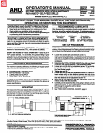
PAR-A-MATIC® SELF-FEED DRILLS
Models 8255-A( )-( ) and 8355A( )-( )
Revised: 11-20-98
Form:
1612-2
IMPORTANT: READ THIS MANUAL CAREFULLY BEFORE INSTALLING,
OPERATING OR SERVICING THIS EQUIPMENT.
OPERATING AND SAFETY PRECAUTIONS
RECOMMENDED LUBRICANTS
l
Keep hands and clothing away from rotating end of tool.
l
Wear suitable eye protection while operating tool.
l
Disconnect air supply from tool before removing/installing bit
or performing other maintenance procedures.
ROUTINE LUBRICATION REQUIREMENTS
Lack of or an excessive amount of lubrication will affect the perfor-
mance and life of this tool. Use only recommended lubricants at
below time intervals:
EVERY 8 HOURS OF TOOL OPERATION - Fill air line lubricator
reservoir of recommended F.R.L. with spindle oil (29665).
EVERY 180 HOURS OF TOOL OPERATION - Inject NLGI #1
“EP” grease (33153), 1 to 2 strokes, thru grease filling in gear
housing. NOTE: Spindle must be extended from outer sleeve suf-
ficiently to expose grease fitting in gear housing. Gearing should
contain approximately 1/8 oz. (3.5 g) of grease per set of gears.
AIR SUPPLY REQUIREMENTS
For maximum operating efficiency, the following air supply specifi-
cations should be maintained to this air tool:
l
AIR PRESSURE - 90 PSIG (6 bar)
l
AIR FILTRATION - 56 micron
. LUBRICATED AIR SUPPLY
l
HOSE SIZE - 5/16” (8 mm) I.D.
An ARO® model C28221-810 air line FILTER/REGULATOR/LU-
BRICATOR (F.R.L.) is recommended to maintain the above air
supply specifications.
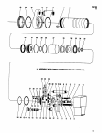
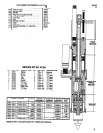
MOUNTING
The nose end of the outer sleeve (43) is provided with 2” - 16 L.H.
threads (remove thread guard [49] for use) and a 2” x 1-1/8” long
pilot diameter for fixture mounting. Foot and flange type mounting
brackets are available for tool mounting.
After disassembly is complete, all pans, except sealed or shielded
bearings, should be washed with solvent. To relubricate parts, or
for routine lubrication, use the following recommended lubricants:
Where Used
Air Motor
29665
1 qt. Spindle Oil
“0” Rings 8 Lip Seals 36480
4 oz. Stringy Lubricant
Gears and Bearings 33153
5 lb. "EP" - NLGI #1 Grease
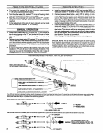
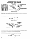
SET-UP PROCEDURE
WARNING: Keep clear of rotating end of unit with hands and/or
clothing. Keep fingers/hands from being pinched between hous-
ing or valves and adjustment screws and/or trip bracket.
l
l
0
0
0
l
l
l
l
l
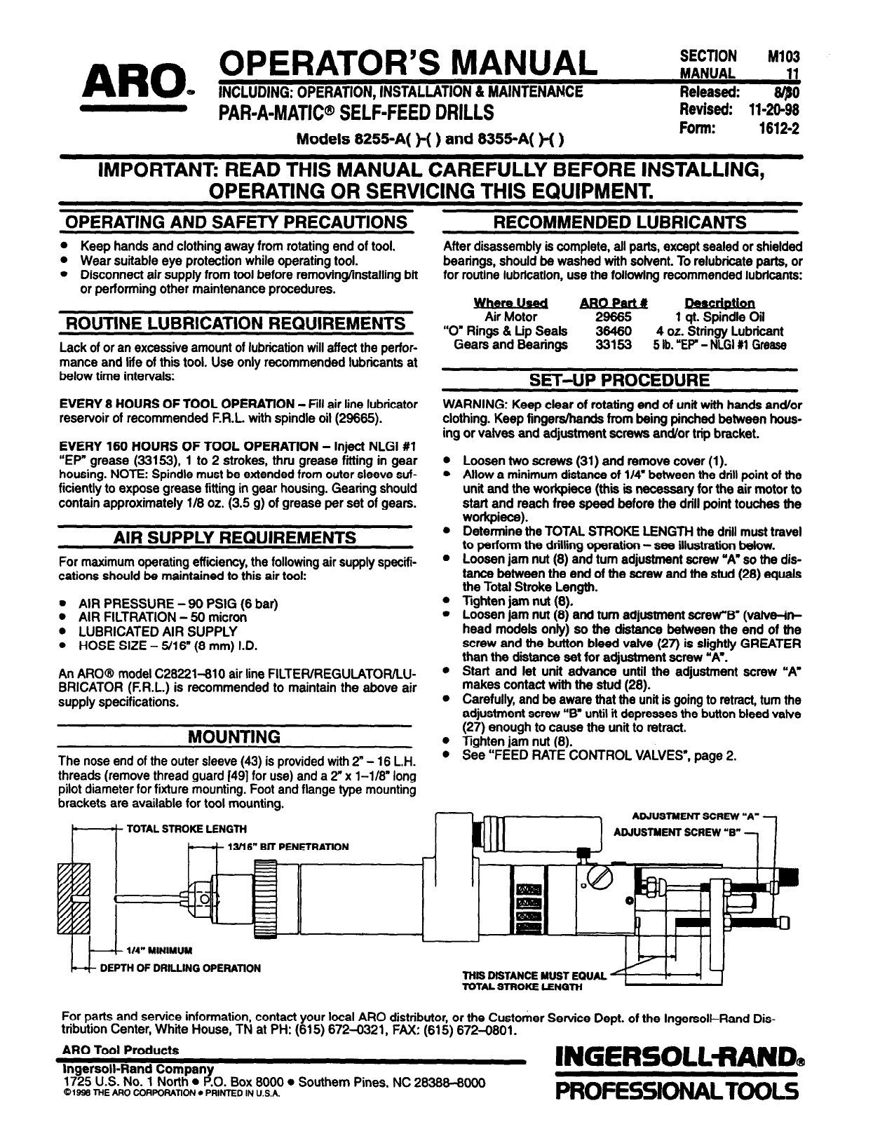
Loosen two screws (31) and remove cover (1).
Allow a minimum distance of 1/4" between the drill point of the
unit and the workpiece (this is necessary for the air motor to
start and reach free speed before the drill point touches the
workpiece).
Determine the TOTAL STROKE LENGTH the drill must travel
to perform the drilling operation - see illustration below.
Loosen jam nut (8) and turn adjustment screw "A” so the dis-
tance between the end of the screw and the stud (28) equals
the Total Stroke Length.
lighten jam nut (8).
Loosen jam nut (8) and turn adjustment screw ”B" (valve-it+
head models only) so the distance between the end of the
screw and the button bleed valve (27) is slightly GREATER
than the distance set for adjustment screw “A,.
Start and let unit advance until the adjustment screw “A".
makes contact with the stud (28).
Carefully, and be aware that the unit is going to retract, turn the
adjustment screw “B" until it depresses the button bleed valve
(27) enough to cause the unit to retract.
Tighten jam nut (8).
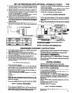
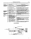
See “FEED RATE CONTROL VALVES”, page 2.
For parts and service information, contact your local ARO distributor, or the Customer Service Dept. of the Ingersoll-Rand Dis-
tribution Center, White House, TN at PH: (615) 672-0321, FAX: (615) 672-0801.
ARO Tool Products
Ingersoll-Rand Company
1725 U.S. No. 1 North
P .O. Box 8000
l
Southern Pines, NC 28388-8000
©1998 THE ARO CORPORATION l
PRINTED IN U.S.A.