RAPID CHARGER
KSC-24
SERVICE MANUAL
Circuit Description
■ Power Supply Section
1. The power supply generates constant current (1.1A)
from the input voltage (rated 15V DC) from the adapter.
2. IC101 is a DC/DC converter.
3. R117 is a resistor for current detection.
4. R110 and R111 are resistors for no-load voltage detec-
tion (non-load voltage : 14V).
5. IC201 is a power supply/reset IC for the microcomputer
(IC202).
· Power output : 5V
· Reset output : “H” (Normal)
· After reset : “L”
■ Charging Control Section
1. The microcomputer (IC202) controls the following;
· Peak detection (Detected when fully charged, pin 27 of
IC202)
· Temperature control (Pin 2)
· Detection of abnormality, such as a short terminal (Pin
27)
· LED control (Red : Pin 21, Green : Pin 22)
· Trickle charging (Pin 18)
· Quick charging (Pin 17)
2. X201 is an oscillator that generates clocks for the micro-
computer (4MHz).
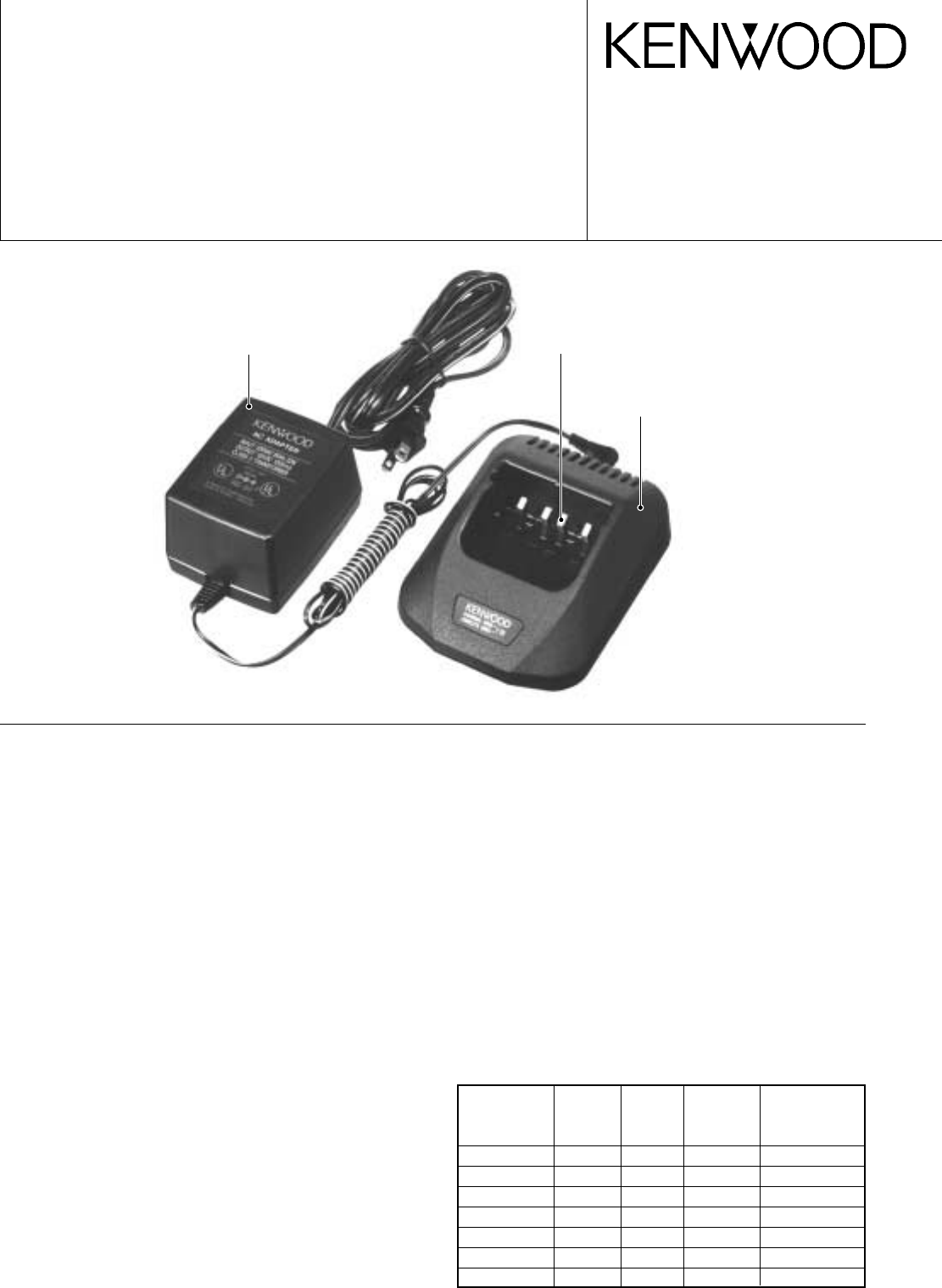
AC adapter
(W08-0523-15) : K
(W08-0524-15) : E
(W08-0939-05) : T
Relay terminal
(E23-1058-08) x 4
Cabinet (Upper)
(A02-3626-08)
© 2001-5 PRINTED IN JAPAN
B51-8583-00
(
N
)
1775
■ Charging Switch Section
1. Q201 is a transistor that turns quick charging on and off.
2. Q202 is a transistor that turns trickle charging on and off.
3. The resistor (R204) determines the leakage current.
■ Display Section
1. LED201 is a two-color LED that indicates the charging
state.
2. Red on ............... Quick charging or warming up
Green on ............ Charging is complete
Red blinking ....... Abnormal (short terminal, short bat-
tery, or open terminal)
Charging
The charging time for each pack is shown in the table.
Battery Battery Voltage
Battery Approximate
Pack Type (Volts)
Capacity Charging Time
(mAh) (Minutes)
KNB-14 Ni-Cd 7.2 600 40
KNB-15A Ni-Cd 7.2 1100 60
KNB-16A Ni-Cd 7.2 1100 60
KNB-17A Ni-Cd 7.2 1500 80
KNB-20N Ni-MH 7.2 1600 80
KNB-21N Ni-MH 7.2 1600 80
KNB-22N Ni-MH 7.2 2100 110
Photo is K type.


