


. A complete Parts List is available at www.MillerWelds.com
OM-1327 Page 22
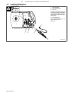
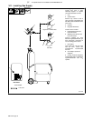
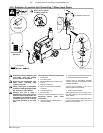
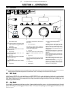
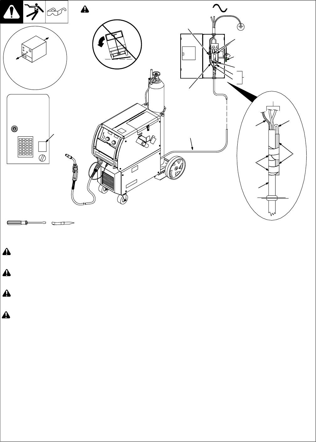
3-16. Selection A Location And Connecting 1-Phase Input Power
Ref. 803 543-D / 803 766-A
Tools Needed:
3
2
7
6
4
! Installation must meet all National and
Local Codes - have only qualified
persons make this installation.
! Disconnect and lockout/tagout input
power before connecting input
conductors form unit.
! Always connect green or green/yellow
conductor to supply grounding terminal
first, and never to a line terminal.
! Warning: This unit is either a
200/230/460 ac input voltage model or
460/575 ac input voltage model. See
rating label on unit and check voltage
available at site to be sure it matches
the voltage specified on the rating
label.
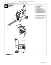
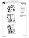
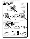
Three Conductor Power Cord Preparation
1 Rating Label
2 Input Power Cord
3 Black And White Input Conductors (L1
And L2)
4 Red Input Conductor
5 Green Or Green/Yellow Grounding
Conductor
6 Insulation Sleeving
7 Electrical Tape
Insulate and isolate red conductor as shown.
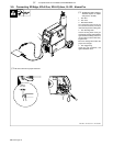
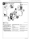
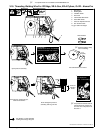
Disconnect Device Input Power
Connections
8 Disconnect Device (switch shown in
the OFF position)
9 Disconnect Device Grounding Terminal
10 Disconnect Device Line Terminals
Connect green or green/yellow grounding
conductor (see Item 5) to disconnect device
grounding terminal first.
Connect input conductors L1 and L2 to
disconnect device line terminals.
11 Over-Current Protection
Select type and size of over-current protec-
tion using Section 3-13 (fused disconnect
switch shown).
Close and secure door on disconnect device.
Remove lockout/tagout device, and place
switch in the On position.
5
1
Rear Panel
18 in (457 mm)
for airflow
! Do not move or operate
unit where it could tip.
=GND/PE Earth Ground
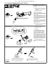
8
1
5
3
9
10
11
L1
L2
2