


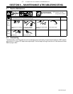
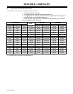
. A complete Parts List is available at www.MillerWelds.com
OM-1327 Page 45
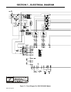
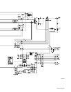
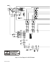
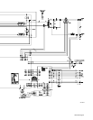
SC-187 212-A
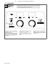
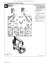
. All directions are in reference to the
front of the unit. All circuitry referred to
is located inside the unit.
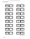
S Help 0
Indicates overheating on left side of unit
(displays flash between OVER TEMP and
HELP 1). Unit will shutdown until internal
temperature drops within operational range.
S Help 1
Turn off primary input power and check input
voltage per primary voltage rating of welder,
and correct if necessary. If HELP 1 persists,
this Indicates a communication error
between control board PC1 and user
interface board. Contact nearest Factory
Authorized Service Agent.
S Help 2
Indicates overheating on right side of unit
(displays flash between OVER TEMP and
HELP 2). Unit will shutdown until internal
temperature drops within operational range.
S Help 3
Indicates gun trigger was pulled and held
during power up. Release gun trigger and
clear fault condition. Also, this display can
Indicate no open circuit voltage detected
when gun trigger is pulled and no arc
detected within 3 seconds. Turn off primary
input power and contact a Factory
Authorized Service Agent.
S Help 4
Indicates gun trigger was pulled and held for
2 minutes without a welding arc established
or there is a direct short between contact tip
or wire and the workpiece. Release gun
trigger and clear fault condition.
S Help 5
Indicates a malfunction in wire feed system
and/or drive motor overcurrent condition.
Check for proper spool brake adjustment or
obstructions in wire feed system. Clean or
replace liner, wire guides, or contact tip.
S Help 6
Indicates a malfunction in wire feed system
and/or external drive motor overcurrent con-
dition (spool gun or push-pull gun). Check for
proper spool brake adjustment or
obstructions in wire feed system. Clean or
replace liner, wire guides, or contact tip.
S Help 7
Indicates input voltage malfunction (voltage
too high or too low) causing unit to
automatically shut down. Turn off input
primary power and check input voltage per
primary voltage rating of welder. Unit will
operate once input voltage is within
specification and power to unit is turned off
and back on.
S Help 8
Indicates a malfunction in the secondary
power circuit of the unit. Check control board
PC1, and primary and secondary
connections.
S Help 9
Indicates a malfunction in Pulse MIG
function. Check connection between pulse
board and user interface board. Replace
pulse board, if necessary.
S Help 10
Indicates a trigger error when two gun
triggers are activated at the same time.
Release gun triggers to clear error.
S Help 11
Indicates a tach error when tach feedback
signal is not present. Release and press gun
trigger to reset tach signal. If error continues,
contact a Factory Authorized Service Agent.
S Tip Save
Indicates contact tip is directly shorted to
workpiece. Arc shuts off in this condition,
and message resets when tip is not touching
workpiece and gun trigger is released.
S MM 350P
When unit is turned on, this display indicates
that pulse option is installed and operational.
S MM 350
When unit is turned on, this display indicates
that unit is either a MIG only machine or
pulse option is installed but not operational.
S Jog XXX (Wire Feed Speed)
Indicates trigger is pressed, but no arc is
detected. Wire feed speed goes to Jog wire
feed speed after 3 seconds.