


OM-216 244 Page 11
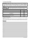
4-2. Electrical Service Guide
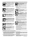
Y CAUTION: INCORRECT INPUT POWER can damage this welding power source. This welding pow-
er source requires a CONTINUOUS supply of 60 Hz (+10%) power at +10% of rated input voltage. Phase
to ground voltage shall not exceed +10% of rated input voltage. Do not use a generator with automatic
idle device (that idles engine when no load is sensed) to supply input power to this welding power
source.
Actual input voltage should not exceed ± 10% of indicated required input voltage. If
actual input voltage is outside of this range, output may not be available.
NOTE
60 Hz Three Phase
Input Voltage 480 575
Input Amperes At Rated Output 55 45
Max Recommended Standard Fuse Rating In Amperes
1
Time-Delay
2
Normal Operating
3
60 50
Min Input Conductor Size In AWG
4
10 10
Max Recommended Input Conductor Length In Feet (Meters)
175
(53)
274
(83)
Min Grounding Conductor Size In AWG
4
10 10
Reference: 2005 National Electrical Code (NEC) (including article 630)
1 Consult factory for circuit breaker applications.
2 “Time-Delay” fuses are UL class “RK5” .
3 “Normal Operating” (general purpose - no intentional delay) fuses are UL class “K5” (up to and including 60 amp), and UL class “H” ( 65 amp and
above).
4 Conductor data in this section specifies conductor size (excluding flexible cord or cable) between the panelboard and the equipment per NEC Table
310.16. If a flexible cord or cable is used, minimum conductor size may increase. See NEC Table 400.5(A) for flexible cord and cable requirements.
Notes