


OM-216 244 Page 29
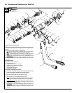
4 Chuck Adapter (2): Unscrew chuck adapter counter clockwise from
cable clamp adapter. Important that chuck adapter is tight on cable
clamp adapter to form a tight connection. An effective way of
removing the adapter is to insert a round rod through two of the
chuck eject holes.
Replace chuck adapter if inside surface or threads are pitted or
damaged.
5 Front Cover Nuts (1): The front cover is held on with two nuts. Use
a 3/4 inch wrench to remove them. Inspect the plastic bearing (4)
for damage or excessive wear.
6 Front Cover (5): If gun is equipped with a plunge dampener it is
located in the front cover. Inspect front cover for cracks and replace
if cracked. The front cover prevents dirt from entering the internal
mechanism and maintains alignment of internal components.
7 Plunge Dampener (7): The dampener is inside the front cover. It
pulls straight out and pushes straight back in. When the plunge
dampener is activated by a finger it should offer continuous
resistance over the entire range of travel. The plunger should then
return, by itself, to full extension. If this is not the case the dampener
needs to be replaced.
8 Cable Clamp Adapter (8): Remove two #10−32 x 5/8 socket head
cap screws (6) from cable clamp adapter. The cable clamp adapter
will separate from the lifting rod. Maneuver the cable clamp adapter
forward between the leg inserts. Remove the #8−32 x 1/2 cap
screw (11) from the back of the cable clamp adapter (8).
Inspect threads on cable clamp adapter. If threads are damage re-
place cable clamp adapter. This item transfers all the weld current.
If there is damage to the threads, arcing will continue and poten-
tially fuse all the components together.
9 Lifting Mechanism: The lifting mechanism consists of the lifting rod
(12), main spring (13), lift release (14), moveable core (15−20) and
core return spring (21). To disassemble, press the lift release ring
tight against the moveable core and pull the lifting rod out of the
assembly. All components listed above, will come apart.
10 Lifting Rod (12): Inspect lifting rod for wear or damage. The brass
inserts should show no signs of loosening. The steel shaft should
not have any nicks on it. Run a finger over the shaft. If you can feel
grooves from the lifting bearing then the lifting rod is worn out.
Typically the lifting rod and lift bearing should be replaced as a set.
When reassembling, the shaft should have a light film of grease (a
lithium based grease) applied.
11 Disassembly of Moveable Core (15 - 20): Remove snap ring (20)
from shaft (18) of core assembly. The snap ring acts as a spring
seat and is important to maintain proper spring tension. Where the
core assembles into the bearing housing is another retaining ring
(19). This retaining ring can be removed with a small flat bladed
screw driver. After removing the second retaining ring the bearing
housing (15) will separate from the core shaft. The lift bearing (16)
and the lift bearing spring (17) can now be removed.
When reassembling the lift bearing cage must oriented toward the
lift bearing spring. Put a light film of grease (such as a lithium based
grease) over the lift bearing and the lift bearing spring.
12 Handle Covers (35): Remove 3 flat head screws (36 - 37) that retain
the handle cover. Inspect handle cover for breakage.
13 Weld Cable (40): The weld cable can lift out of the gun body. Be
careful unthreading the internal weld cable (9) from inside the body.
The internal and external weld cables can be unscrewed from the
weld cable anchor plate (32). Note the orientation of the weld cable
anchor plate. The radius corner goes toward the top of the body.
Inspect the internal weld cable for frayed or broken wires. If starting
to fray, the internal cable should be replaced.
Inspect weld cable for fraying. Also inspect strain relief (38) for
tears. Inspect cable jacketing for breaks, cuts or tears. If cable
shows signs of damage or wear it should be replaced. In addition,
inspect the weld−lok connector (39). If pitted or damaged, replace.
Inspect weld cable to camlok joint to ensure there is no fraying of
the weld cable.
14 Control Cable (42) (if desired): The control cable is removed by
cutting the wires by the splice connectors. Inspect the control cable
for damage. This includes the strain relief (41) and the insulating
jacketing. If damaged, replace the control cable.
When reinstalling the control cable, there are typically two different
color schemes.
Scheme one: Black and White wires connect to the trigger - Blue
and Brown Wiresconnect to the coil
Scheme two: Black and White wires connect to the trigger - Red and
Green wires connect to the coil.
Make sure all crimp connections are tight and there is no opportuni-
ty for electrical shorting.
15 Trigger Switch (31): The trigger switch is a screw in style. Grabbing
it can be difficult. A 1/2” collet is the ideal removal tool. Use an ohm
meter to check trigger functionality.
16 Rear Cap (29): Unscrew and remove. The rear cap prevents dirt
and other contaminates from entering into the gun mechanism.
. Do not use rear of gun as a hammer to check quality of stud weld
for this will damage the rear cap.
17 Adjustable Core (28): Loosen nylon tipped set screw (27) in rear coil
yoke which holds the adjustable core. Completely unscrew and
remove adjustable core.
18 Rear Coil Yoke (26): Loosen the nylon tipped set screw retaining the
rear coil yoke. To perform this the hex key will have to go into the
opening on an angle to reach the set screw. Once the retaining
screw is loosened use a large wrench to unscrew the rear coil yoke.
19 Coil (25): Coil wires (black and red or green and red inside the gun
handle) must be cut prior to coil removal. Cut wires inside the
handle. After coil wires are free, the coil can be pulled straight out
the rear of the gun. Coil condition - check to make sure there is no
varnish odor (a sign of overheating), heavy discoloration (another
sign of overheating) and verify coil resistance at 19 ohms +/− 1 ohm.
20 Front Coil Yoke (24): In front of the coil is the front coil yoke. This
is a tight fit and may be difficult to remove. The front coil yoke
contains a plastic bearing (4). This bearing should be inspected for
wear or damage and replaced if necessary. During reassembly,
make sure the bearing flange is seated in the counterbore on the
front coil yoke. When putting the front coil yoke back into the coil
can, make sure the bearing flange is facing rear of gun.
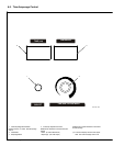
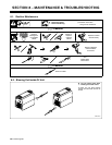
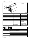
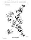
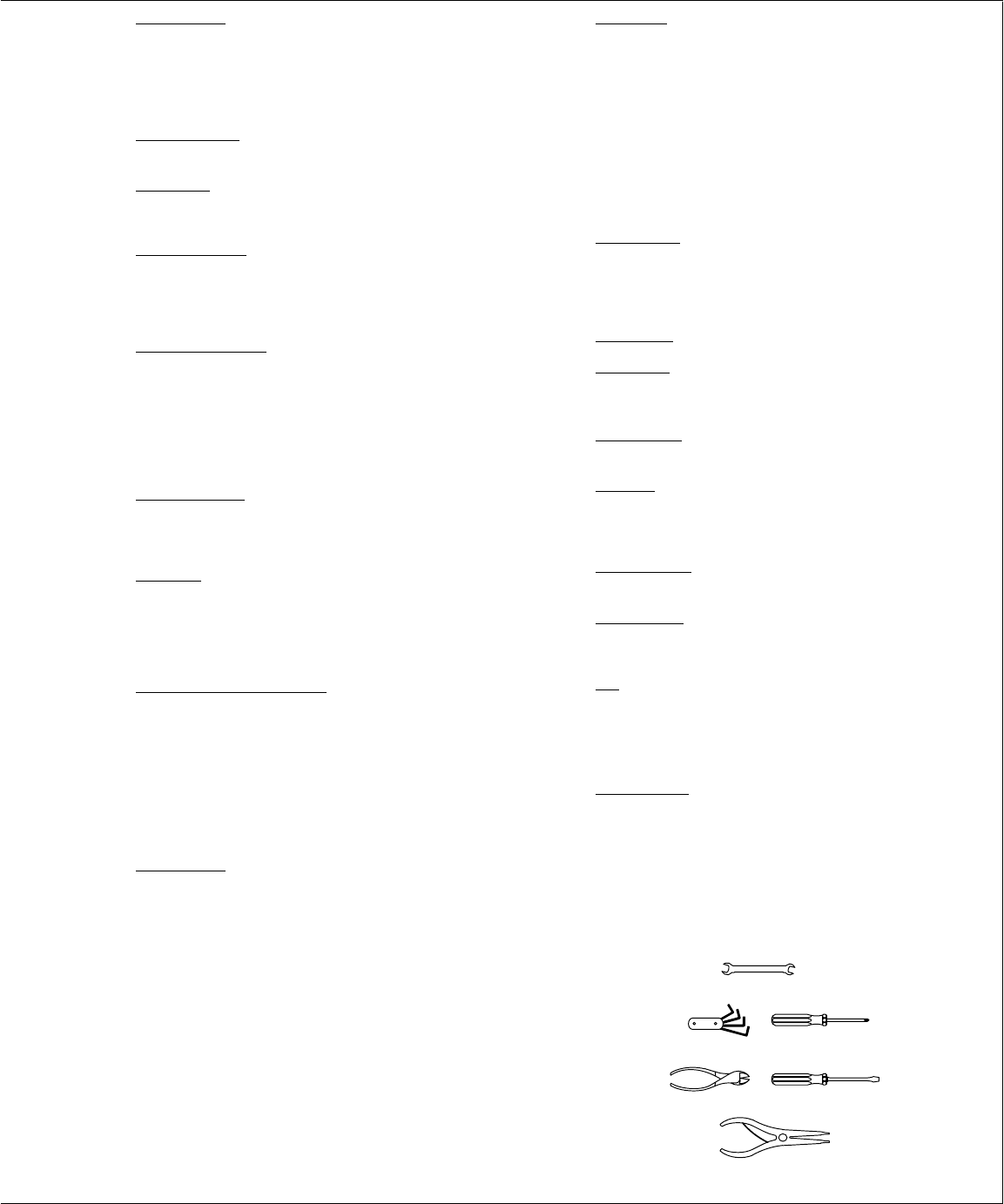
3/4 in
Tools Needed: