


OM-293 Page 12
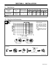
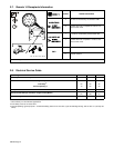
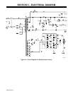
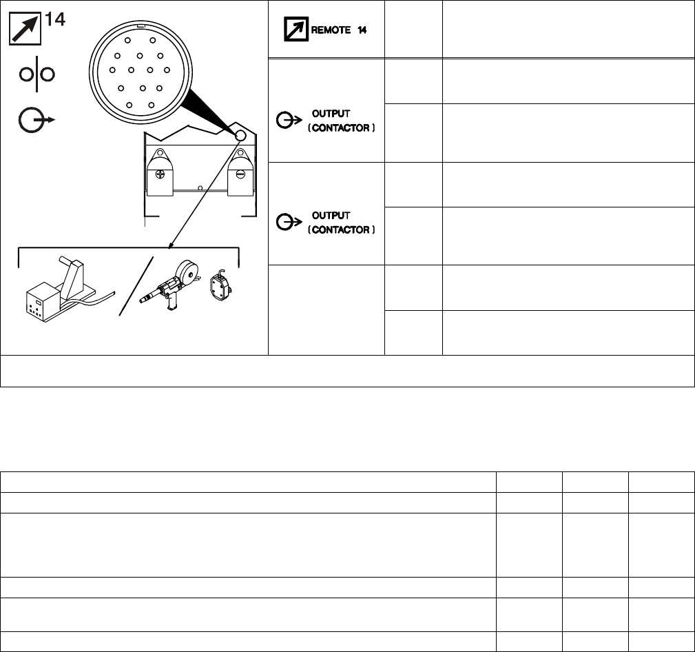
2-7. Remote 14 Receptacle Information
AJ
K
I
Socket* Socket Information
B
K
I
C
L
NH
D
M
G
24 VOLTS AC
A 24 volts ac. Protected by circuit breaker CB2.
E
F
24 VOLTS AC
B Contact closure to A completes 24 volts ac con-
tactor control circuit.
115 VOLTS AC
I 115 volts ac. Protected by circuit breaker CB1.
115 VOLTS AC
J Contact closure to I completes 115 volts ac con-
tactor control circuit.
G Circuit common for 24 and 115 volts ac circuits.
Ref. 121 470-E / Ref. 192 412
GND
K Chassis common.
*The remaining sockets are not used.
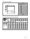
2-8. Electrical Service Guide
Input Voltage 200 230 460
Input Amperes At Rated Output 46 40 20
Max Recommended Standard Fuse Rating In Amperes
1
Time-Delay
2
50 50 25
Normal Operating 3 70 60 30
Min Input Conductor Size In AWG/Kcmil 8 8 12
Max Recommended Input Conductor Length In Feet (Meters)
89
(27)
118
(36)
188
(57)
Min Grounding Conductor Size In AWG/Kcmil 8 10 12
Reference: 1999 National Electrical Code (NEC)
1 Consult factory for circuit breaker applications.
2 “Time-Delay” fuses are UL class “RK5” .
3 “Normal Operating” (general purpose – no intentional delay) fuses are UL class “K5” (up to and including 60 amp), and UL class “H” ( 65 amp and
above).