


OM-293 Page 14
SECTION 3 – OPERATION
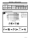
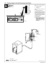
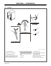
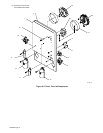
3-1. Controls
1 Voltage Range Switch
Use switch to select voltage range.
2 Voltage Adjustment Switch
Use switch to adjust voltage within range se-
lected by Voltage Range switch. Each posi-
tion of the switch is a change of 2 volts.
Y Do not change position of Voltage
Range switch or Voltage Adjustment
switch while welding. Arcing can da-
mage contacts, causing connections
to fail.
3 Power Switch
4 Pilot Light
5 Circuit Breaker CB2
If CB2 opens, the 24 volts ac output to the Re-
mote 14 receptacle stops.
6 Circuit Breaker CB1
If CB1 opens, the 115 volts ac output to the
Remote 14 receptacle stops.
Press button to reset circuit breakers.
1
3
2
Ref. 121 471-H / Ref. 192 412
6
5
4