


31
35
41
34
30
36
28
40
14
39
4
63
38
37
8
7
3
43
45
44
46
47
48
49
50
51
52
53
54
58
52
57
56
59
60
55
61
62
5
33
1
21
8
29
22
15
16
2
27
67
66
42
68
69
13
17
25
32
18
10
9
23
26
24
24 30 31 34
35 36 41
64
23
19
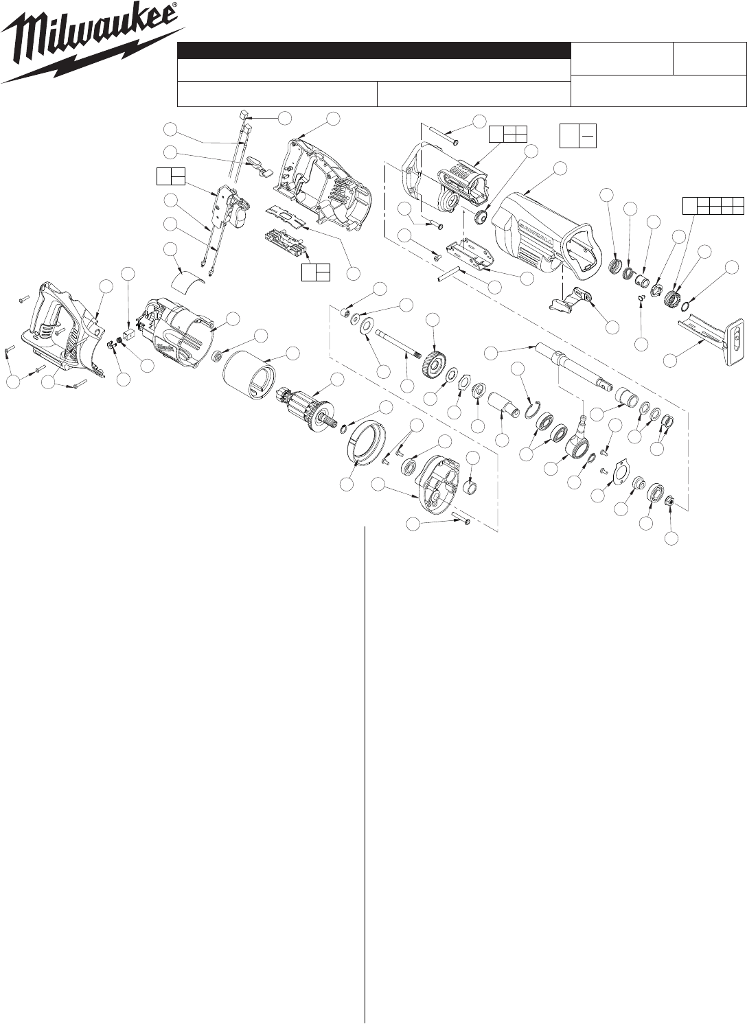
FAN
S
I
DE
>>
68
69
65
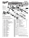
EXAMPLE:
Component Parts (Small #)
Are Included When Ordering
The Assembly (Large #).
54-40-7000
A56A
CORDLESS SAWZALL
®
0719-20
FIG. PART NO. DESCRIPTION OF PART NO. REQ.
1 02-04-0719 Ball Bearing (1)
2 02-04-5130 Ball Bearing (1)
3 02-50-2150 Needle Bearing (1)
4 05-88-0302 K50 x 60mm Washer Hd. PT Screw (2)
5 05-88-8309 K50 x 35mm Washer Hd. PT Screw (1)
7 06-82-5363 8-32 x 1 Washer Hd. Taptite T-20 Screw (2)
8 06-82-7253 8-32 x .38 Taptite T-20 Screw (3)
9 06-82-7261 6-19 x .687 Slotted Plastite T-15 Screw (4)
10 06-82-7276 6-19 x 1.00 Slotted Plastite T-15 Screw (2)
13 12-20-0719 Service Nameplate Kit (1)
14 28-14-0997 Gearcase (1)
15 16-01-2121 Service Armature (1)
16 18-01-2120 Service Field (1)
17 22-20-0860 Brush Tube (2)
18 22-32-0400 Brush Spring Clip (2)
19 22-56-0975 Connector Block Assembly (1)
21 28-28-0719 Diaphragm (1)
22 31-05-0719 Baffl e (1)
23 -------------- Connector Block Cover (1)
24 31-15-0511 Spring Cover (1)
25 31-44-0718 Right Handle Half (1)
26 31-44-0719 Left Handle Half (1)
27 31-50-0019 Motor Housing (1)
28 31-52-0090 Shoe Release Lever (1)
29 34-60-0920 External Retaining Ring (1)
30 34-60-3680 Retaining Ring (1)
31 40-50-0161 Torsion Spring (1)
32 40-50-8840 Brush spring (2)
33 42-24-0620 Rear Spindle Bearing (1)
34 42-50-0076 Front Cam (1)
35 42-50-0077 Rear Cam (1)
36 44-60-0626 Lock Pin (1)
37 44-60-1635 Shoe Pin (1)
38 44-66-0880 Shoe Retainer (1)
39 45-12-0999 Gearcase Insulator (1)
40 45-16-0645 Shoe Assembly (1)
41 45-22-0081 Sleeve (1)
42 45-24-0719 Lock Off Lever (1)
43 45-88-1555 Washer (1)
44 40-50-8850 Disc Spring (1)
45 42-12-0155 Wobble Shaft Axel (1)
46 32-40-0719 Intermediate Gear (1)
47 43-06-0685 Metal Plate (1)
48 43-06-0676 Bronz Plate (1)
49 43-78-0525 Drive Hub (1)
50 36-92-0501 Wobble Shaft (1)
MILWAUKEE ELECTRIC TOOL CORPORATION
13135 W. LISBON RD., BROOKFIELD, WI 53005
Drwg. 4
REVISED BULLETIN DATE
SPECIFY CATALOG NO. AND SERIAL NO. WHEN ORDERING PARTS
SERVICE PARTS LIST
STARTING
SERIAL NO.
BULLETIN NO.
CATALOG NO.
WIRING INSTRUCTION
00
0
FIG. PART NO. DESCRIPTION OF PART NO. REQ.
51 34-80-2600 Internal Retaining Ring (1)
52 02-04-1510 Ball Bearing (3)
53 30-72-0085 Wobble Plate (1)
54 34-60-1315 Retaining Ring (1)
55 06-82-7253 8-32 x 3/8" Pan Hd. Slt. Taptite T-20 (2)
56 44-86-0055 Bearing Retainer (1)
57 45-36-1445 Spacer (1)
58 06-55-3790 5/16-24 Spinlok Hex Nut (1)
59 38-50-0680 Reciprocating Spindle (1)
60 --------------- Front Spindle Bearing (1)
61 --------------- Felt Seal (2)
62 --------------- Washer (2)
63 42-52-0380 Bearing Cap (1)
64 14-46-1011 Steel Quik-Lok Blade Clamp Kit (1)
65 23-66-1719 Switch Assembly (1)
66 22-18-1719 Carbon Brush Assembly - Black (1)
67 22-18-0719 Carbon Brush Assembly - Red (1)
68 23-94-0016 Leadwire Assembly - Black (1)
69 23-94-0015 Leadwire Assembly - Red (1)
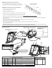
LUBRICATION
Place 1/2 oz. of type "Y" grease, No. 49-08-5270,
in diaphragm cavity near the needle bearing.
Place 2-1/2 oz. of type "L" grease, No. 49-08-4175,
in cavity in front of bearing plate in the gearcase.
Place a heavy coat of Type "X" contact grease, No. 49-08-5000,
in/on terminals of wires #68 and #69 after installing into
connector block (19) but prior to snapping on the cover (23).
SEE REVERSE SIDE
NOTES:
Press rear spindle bearing (33) fl ush to -.030 from front exterior face
in diaphragm boss (21).
Torque spinlok hex nut (58) to 180 in./lbs. to 210 in./ lbs.
Retaining ring (51) is to be installed with the beveled side away from
the bearing (52).
Press front spindle bearing (60) fl ush to .015 below interior surface
of gearcase (14).
Needle bearing (3) is to be pressed from the open end fl ush to ±.005
to face of bearing boss of diaphragm (21).
Wobble plate retaining ring (51), to face wobble shaft (50) in assembly.
Remove brush tubes (17) prior to removing armature assembly (15) from
motor housing (27).
Install brush tubes (17) into motor housing (27) only after armature
assembly (15) has been secured into motor housing (27).
NOTES:
Seal side of bearing (2)
to face armature (15).
Stamped arrows (>>) on
fi eld casing (16) to face
armature fan (11).
Concave side of connector
block cover (23) to face
connector block (19).
14
60 61
62
Aug. 2006