


WIRING INSTRUCTIONS
BULLETIN
58-01-0170
Feb. ‘72 1
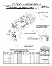
Field Lead No.2 Should Be Cut So That
l-318 Extends Past End of Handle.
Field wire No.2 should run behind and
over mounting boss and across brush-
holder boss.Both field wire No.2 and
brushholder wire No.3 should run
across top of switch and in wire clamp.
/
Wire terminals should be bent
at 90 degree angles after being
connected to switch.
s 1 * 23-66-0580 Switch used on 5360 tools.
\ A
Use 45-30-0050 shock ob
between switch and outsi
of handle cavity on 5360
Ti ‘\
USE LOCKWASHERSUNDER
ALLSWITCHTERMINALS.
NOTE:
*LL L.EllDSM".sT BE HELDTOf 1/P
ALLFlELDlEhDSTOBEUEhSUREDFROM
ANDPERPENDlC"LARTOL*MINATIONS.
ALL LEADLENTGHSARE
BEFORESnuPPING
Where Terminal and Connector Combinations are Specified, See Parts Chart
For Part No. and Quantity. See Dwg. For Actual Hookup.
WIRING SPE
color
Red
Brown
:IFICATIONS
Wire
Wire ~~
Latf
Color No. . In.
Greetl 6 Cord 3
White
Black
White
23-74-0330
Form OE-24