6-161
SPD
1
2
3
4
4
6
7
8
6.8 Other Convenient Instructions
6.8.7 Pulse density measurement (SPD)
1. With the SPD instruction, the argument device data is registered in the work
area of the CPU module and counting operation is processed as a system
interrupt. (The device data registered in the work area is cleared by turning the
execution command OFF, or turning the STOP/RUN switch STOP RUN.) For
this reason, the pulses that can be counted must have longer ON and OFF
times than the interrupt interval of the CPU module. The interrupt interval of
individual modules is shown below:
2. • When the High Performance model QCPU or Process CPU is used:
The instruction is not processed when n = 0.
3. The SPD instruction can be used as many as 6 times within all the programs
being executed. The seventh and the subsequent SPD instructions are not
processed.
4. While the measurement is in execution (while the command input is ON) by the
SPD instruction, the setting value cannot be changed. Turn OFF the command
input before changing the setting value.
Operation Error
(1) In the following case, an operation error occurs, the error flag (SM0) turns ON, and an error
code is stored into SD0.
• The device specified by exceeds the range of the corresponding device.
(For the Universal model QCPU only.) (Error code: 4101)
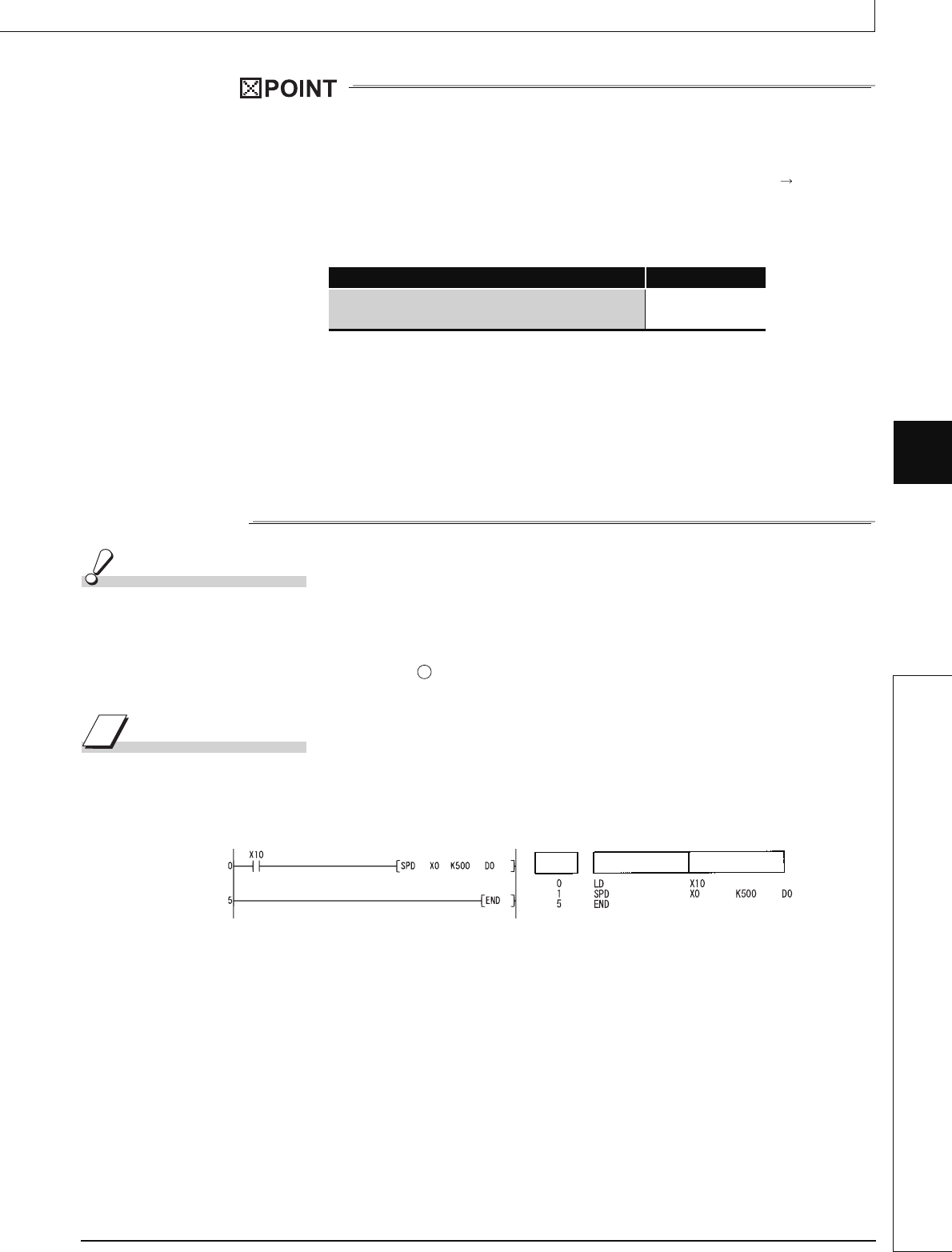
Program Example
(1) The following program measures the pulses input to X0 for a period of 500 ms when X10
goes ON, and stores the result at D0.
[Ladder Mode] [List Mode]
CPU Module Type Name Interrupt Interval
High Performance model QCPU, Process CPU,
Universal model QCPU
1 ms
S
Step
Instruction
Device


