2-11
2
3
4
4
6
7
8
2.4 Basic instructions
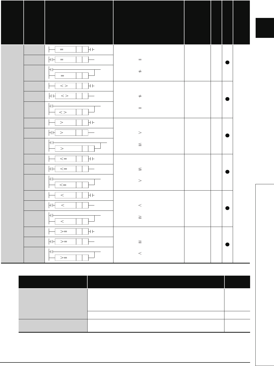
2.4.1 Comparison operation instructions
Table 2.10 Comparison Operation Instructions (Continued)
*1: The number of steps may vary depending on the device and type of CPU module being used.
Note 1) When using a High Performance model QCPU, Process CPU or Redundant CPU,
the number of steps increases but the processing speed becomes faster.
Note 2) The number of steps may increase due to the conditions described in Section 3.8.
Category
Instruction Symbol
Symbol Processing Details
Execution
Condition
Number of Basic Steps
Subset
See for Description
BIN 32-bit
data
comparisons
LDD=
• Conductive status when
(S1+1, S1) (S2+1, S2)
• Non-Conductive status when
(S1+1, S1) (S2+1, S2)
*1
6-4
ANDD=
ORD=
LDD<>
• Conductive status when
(S1+1, S1) (S2+1, S2)
• Non-Conductive status when
(S1+1, S1) (S2+1, S2)
*1
ANDD<>
ORD<>
LDD>
• Conductive status when
(S1+1, S1) (S2+1, S2)
• Non-Conductive status when
(S1+1, S1) (S2+1, S2)
*1
ANDD>
ORD>
LDD<=
• Conductive status when
(S1+1, S1) (S2+1, S2)
• Non-Conductive status when
(S1+1, S1) (S2+1, S2)
*1
ANDD<=
ORD<=
LDD<
• Conductive status when
(S1+1, S1) (S2+1, S2)
• Non-Conductive status when
(S1+1, S1) (S2+1, S2)
*1
ANDD<
ORD<
LDD>=
• Conductive status when
(S1+1, S1) (S2+1, S2)
• Non-Conductive status when
(S1+1, S1) (S2+1, S2)
*1
ANDD>=
ORD>=
Component Device
Number of
Steps
High Performance model QCPU
Process CPU
Redundant CPU
• Word device: Internal device (except for file register ZR)
• Bit device: Devices whose device Nos. are multiples of 16, whose digit
designation is K8, and which use no Indexing.
• Constant: No limitations
5
Note 1)
Devices other than above
3
Note 2)
Basic model QCPU
Universal model QCPU
All devices that can be used
3
Note 2)
DS1S2
DS1S2
DS1S2
DS1S2
DS1S2
DS1S2
DS1S2
D
S1 S2
S1 S2D
DS1S2
DS1S2
DS1S2
DS1S2
DS1S2
D
S1 S2
DS1S2
DS1S2
DS1S2


