


Pacic Accessory Corporation - Santa Ana, CA 92705
Tech Support 866-931-8021 • www.pac-audio.com
DISCLAIMER: Under no circumstances shall the manufacturer or the distributors of the C2R-VW parts be held liable for consequential damages sus-
tained in connection with the C2R-VW. The manufacture and it’s distributors will not, nor will they authorize any representative or any other individual to
assume obligation or liability in relation to the C2R-VW other than its replacement.
10-07-09
9
1
23456
78
1011
1 amp
fuse holder
#1
#2
Accessory Output
+12volts 1amp max.
Pacific Accessory Corporation
VW Radio Replacement Interface
2002-2007
6 pin
Blue/White = Vehicle Year Select
Black/White = N/A
Green = Reverse output (2005.5-2007)
Orange/White = Parking Light output
Violet/ White = Vehicle Speed Sense (VSS) output
Red/White = Parking Brake output (2005.5-2007)
Yellow = +12v Constant
Black = ground
Gray = Right Front (+)
Gray/Black = Right Front (-)
White = Left Front (+)
White/Black = Left Front (-)
Violet = Right Rear (+)
Violet/Black = Right Rear (-)
Green = Left Rear (+)
Green/Black = Left Rear (-)
Red = +12v Accessory output
To optional SWI-CAN interface for retaining steering wheel audio controls
11 pin
16 pin
J1850
Class 2
VPW
Class 2
J1850
100011101111001001101100
111010000110110111001100
Arbitration
EOD
CRC
100011101111001001101100
111010000110110111001100
Class 2
Class 2
J1850
Radio Replacement interface for Volkswagen
Use for Aftermarket Navigation radios that require Vehicle
Speed Sense, Reverse, Parking Brake and Illumination inputs.
C2R-VW
Installation:
1. Connect the aftermarket radio’s front and rear speaker wires to the 16 pin plug.
3. The 16 pin harness has a yellow and a black wire. Connect the yellow to the radio’s +12v constant wire and the black to the
radio’s ground wire.
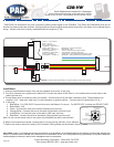
4. The accessory wire is located on the 6 pin harness - connect this wire to the radio’s accessory wire. The accessory wire
supplies +12v, 1 amp max, when key is in the accessory or Ignition position. If more current is needed refer to Fig. 1.
5. 11 pin plug:
Blue/White - For 2002-2005, Connect this wire to the Battery 12v source. For 2005.5-2007, Insulate and DO NOT USE! 1.
Black/White - N/A.2.
Green - Connect this wire to the radio’s Reverse input wire only.3.
Orange/White - Connect this wire to the radio’s Illumination input wire only.4.
Violet/White - Connect this wire to the radio’s VSS input wire only.5.
Red/White - Connect this wire to the radio’s Parking brake input wire only.6.
Note: Do not connect these wires to any other circuit besides the radio’s wire harness.
6. When all connections are made, connect the 16 pin plug into the vehicle’s 16 pin harness.
7. Refer to the radio’s manual for testing VSS, Reverse, Parking Brake and Illumination inputs (if used).
* 2002-2005 VW vehicles do not have a reverse or parking brake signal on the CAN-Bus. The Green and Red/White wires do not
function for these model year vehicles. Parking brake and reverse signal wires can be found with a volt meter in the vehicles factory
wiring. Vehicle must have a factory installed double din headunit (4” tall).
Fig. 1
(using a SPDT relay)
85 86
30
87
87a
Ground
High Current 12v
(Fused)
12v Acc.
From
Interface
New High
Current Output
Diode 1N4005
or equivelant