


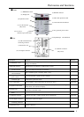
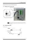
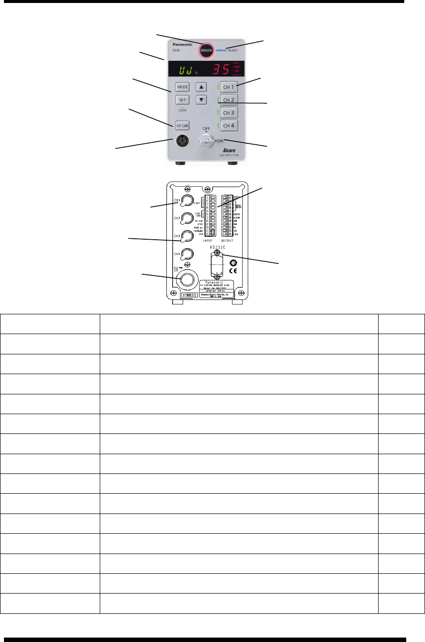
Part names and functions
5
Description Function Remark
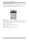
(1) EMISSION switch
UV is irradiated and stopped by selected irradiating CH head. Red lamp is turned on
during UV irradiation.
(2) READY indicator Indicates that UV irradiation is enabled (ready to start).
(3) CH1-CH4
operation switch
Selects the LED head channels for irradiation.
(4) CH1-CH4
selector/indicator
Red = irradiation, green = standby, yellow = error
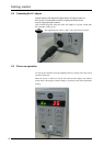
(5) Key operated
power switch
Commences/finishes operation of the controller.
(6) UV sensor
connection port
Connects the special UV sensor. UJ35 only
(7) UV check button Views/calibrates values measured by the special UV sensor UJ35 only
(8) Operation unit switch
Specifies irradiation conditions (intensity and time), replacement time settings, and
initial values, and switches the display.
(9) Display unit
Displays irradiation conditions (intensity and time), replacement time settings, head
temperature, and initial values.
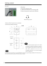
(10) Input/output terminal
block
Connects a PLC, foot switch, or other external device
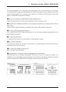
(11) RS232C connector Connects a PC, PLC, or other external device with RS232C. UJ35 only
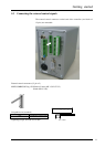
(12) AC adapter connector Connects the special AC adapter.
(13) CH1-CH4 head
connecting connector
Cconnects LED heads.
(14) Protective seal Protects connectors.
(12) AC adapter connector
●
Rear
(7) UV check switch
(only UJ35)
●Front
(11) RS232C connector
(only UJ35)
(13) CH1-CH4 LED head
connecting connector
(10) Input/Output terminal block
(14) Protective seal
(9) Display unit
(8) Operation switch
(6) UV sensor
connection port (only UJ35)
(1) EMISSION switch
(2) READY indicator
(3) CH1-CH4 operation switch
(4) CH1-CH4 selector/indicator
(5) Key operated power switch