


Job Information Type:
Job Name:
Cat. No.:
Lamp(s):
Notes:
"JSQPSU3PBE'BMM3JWFS."tt'BY
We reserve the right to change details of design, materials and finish.
XXXMJHIUPMJFSDPN½1IJMJQT(SPVQt
Lighting Systems F7000-17
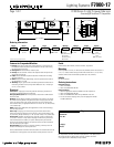
1BHFPG '4FSJFT-JHIU5-PVWFS4JEF-FOT
&
5.77” (14.66cm)
1.63”
(4.14cm)
1
1
5
4
5.770” (14.66cm)
1.304”
(3.31cm)
.750
(1.91cm)
6. Louver Shielding
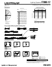
Features for Suspended Modules
1. Housing: Single piece of high purity extruded aluminum, a portion from recy-
cled material. Extruded acrylic lens reveal installed on the top of the housing,
runs the length of the housing.
2. Housing End: Die-cast aluminum, welded in place.
3. End Cap:Die-cast aluminum. Encloses the suspension cable and power feed
cord for the end of the run.
4. Lamps: F28T5 or F54T5HO as specified. By others. Installed from the ceiling
side of the luminaire.
5. Ballast: Electronic. Meets ANSI starting, end-of-life protection and sound rat-
ing specifications. Low THD.
6. Shielding: Integral, regressed flat louver blades punched and formed from fix-
ture housing, finished to match, no light leaks. Blades are .56” (1.42cm) high
on .75” (1.91cm) centers.
Electrical
Connections: 18 gauge pre-wired with polarized cannon plug connectors for
simultaneous mechanical/electrical connection.
Emergency Battery Pack: 90 minute operation, 700 lumens for 54W and 520
lumens for 28W.
Dimming: Advance Mark X standard (no additional wires required); use compat-
ible dimmer. Dimming ballasts using additional control wires (eg Lutron Hi-Lume
or ECO-10, Osram) can be used; consult factory and use X4 or X5 power feeds
with additional leads, as appropriate. Ballast not to exceed 1.25” (3.18cm) wide by
1.20” (3.05cm) high.
iGEN: F7000 accepts iGEN (DALI) with supplemental 2-wire control technology.
Use with X5 power feed.
Power Tray:Code-gauge, die-formed steel, pre-paint white enamel finish;
secured by quarter-turn fasteners for easy access to wiring. Holds ballasts, sock-
ets, and wiring. Accepts ballasts up to 1.25” (3.18cm) wide by 1.20” (3.05cm) high.
Power Feeds: Standard 18/3 power feed is rated for 10 amps. X4 power feed
is 18/4 and is rated for 7 amps. Observe amperage limitations and provide addi-
tional Intermediate Power Cables, as required. When providing an additional
power feed, the through wiring from the previous module must be disconnected
from the cannon plug and capped.
Dual Switching: Use DS option for separate switching of the lamp rows. DS
includes a 4th through wire. Use X4 power feed.
Finish
Powder-coated, baked enamel, white or aluminum, as specified.
Mounting
Cable suspension is on 48” (121.92cm) and 96” (243.94cm) centers and consists of
a 4 1/2” (11.43cm) diameter canopy finished white enamel and a 1/16” (0.16cm)
diameter stainless steel aircraft cable adjustable up to 36” (91.44cm).
Labels
UL, cUL and I.B.E.W.
Ordering Instructions
Individual Fixtures:
1. Order one MODULE.
2. Order one POWER FEED END SET
Continuous Rows:
1. Order the appropriate number of MODULES for the complete run.
2. Order one POWER FEED END SET.
3. Order one INTERMEDIATE CABLE SET per MODULE minus one.
4. For runs that exceed amperage limits, order the appropriate number
of CABLE/CORD SETs.
Ordering Information
F7
Family Series
4
Type Lamps Color Wattage Voltage Length Options
4 2
4 = Block
w/ Lens
4 = Louver 2 = 2 Lamps AL = Aluminum
WH = White
1 = 28W
2 = 54W
3 = 28W Dimming
4 = 28W EM
5 = 54W Dimming
6 = 54W EM
1 = 120v
2 = 277v
4 = 4’ (121.92cm)
8 = 8’ (243.84cm)
X4 = 4 Through
Wires
X5 = 5 Through
Wires
DS = Dual Switch
Complete Ordering Instructions below.
Factory installed ballast disconnect allows the ballast to be disconnected from and
reconnected to incoming power under load without turning the entire circuit off.
Armstrong
®
5FDI;POFÜ$PNQBUJCMF