


– 20 –
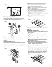
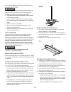
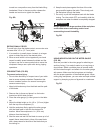
Fig. DD
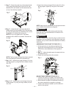
6. If the blade and riving knife are not correctly aligned,
adjustment is needed.
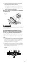
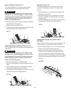
7. Loosen the two larger lock screws (4).
8. Locate the four samll set screws (5) adjacent to the
riving knife lock knob(6). Adjust the small set screws
to move the riving knife according to the position
noted in step 4. Lay the combination square on the
opposite side of the blade and repeat adjustment as
needed.
9. Lightly tighten the two larger lock screws.
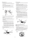
10. Place a square flat against the riving knife to verify
riving knife is vertical and in line with the blade.
11. If needed, use the set screws to bring the riving knife
vertical with the square.
12. Repeat steps 7 and 8 to verify position of riving knife.
13. Fully tighten the two larger lock screws.
Fig. EE
NOTE:
• This table saw is provided with a 10 in. diameter
blade with a body thickness of 1.8 mm (0.07 in.) thick
with a kerf of 2.6 mm (0.1 in.). The riving knife is
2.2 mm (0.09 in.) thick. The blade diameter and the
blade body and kerf dimensions must be properly
matched with the riving knife thickness.
• The maximum radial distance between the riving
knife and the toothed rim of the saw blade is 0.12 in
~ 0.31 in. (3 mm ~ 8 mm)
• The tip of the riving knife shall not be lower than 0.04
in. ~ 0.2 in. (1 mm ~ 5 mm) from the tooth peak.
• The riving knife is thinner than the width of the kerf
by approximately 1/64 in. (0.4 mm) on each side.
• The blade body must be thinner than the thickness
of the riving knife but the blade kerf must be thicker
than the riving knife.
3
2
1
4
5
6
4
5
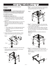
INSTALLING BLADE GUARD ASSEMBLY (FIG. FF, GG)
To avoid injury from an accidental start, make sure
the switch is in the OFF position and the plug is
disconnected from the power source outlet.
• When installing the blade guard, cover the blade
teeth with a piece of folded cardboard to protect
yourself from possible injury.
• Never operate this machine without the blade
guard in place for all through sawing operations.
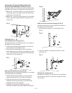
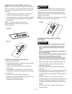
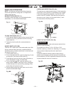
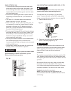
Installing the anti-kickback pawl and blade guard
assembly (Fig. FF)
1. Make sure the blade is elevated to its maximum
height and the bevel is set at 0°. Make sure the bevel
lock handle is tight.
2. Take the anti-kickback pawl assembly (1) and lift up
the locking lever (2) located on top.
3. Place the front of assembly into slot (3) and push
down making sure the assembly is engaged in the slot
(3, 4). There should be no movement of the assembly.
Push down on the locking lever.
Fig. FF
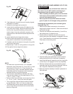
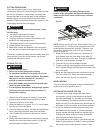
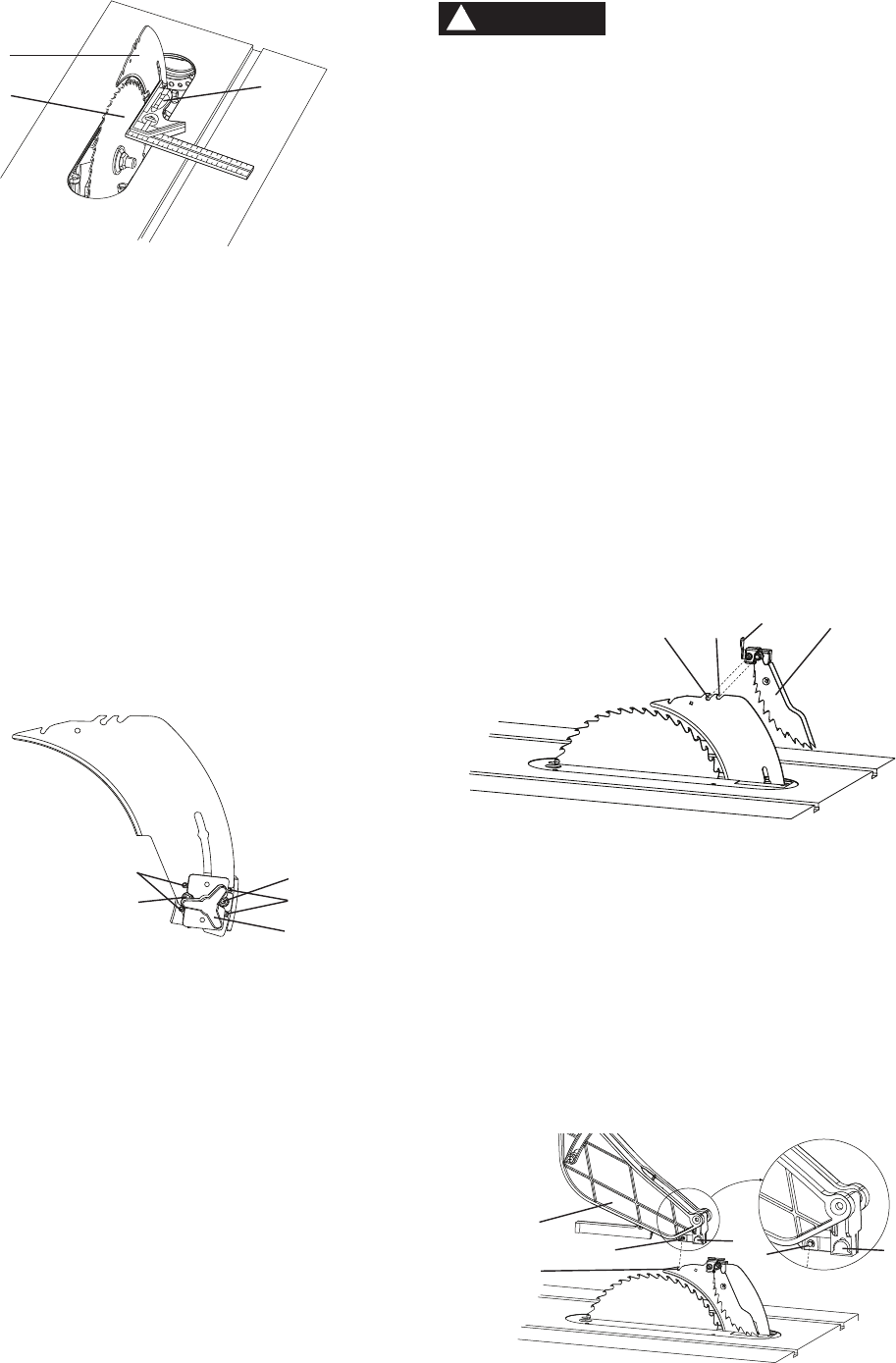
4. Take the blade guard assembly (5) and locate the
sliding locking knob (6) on the back of assembly.
5. Insert the blade guard assembly onto the riving knife
so that the pin (7) engages into slot (8) completely.
6. Slide the locking knob (6) up and press the guard
assembly down so that the entire assembly is flat on
the riving knife. Release the locking knob.
7. Make sure that the assembly is locked in place both in
front and back.
Fig. GG
WARNING
!
1
2
43
6
5
7
8
6
7