


24
OPERATION
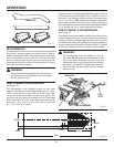
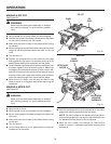
FRONT
RAIL
REAR
LIP
RIP
FENCE
LOCKING
LEVER
SAW
TABLE
WARNING:
To reduce the risk of injury, always make sure the
rip fence is parallel to the blade before beginning
any operation.
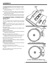
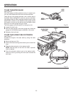
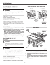
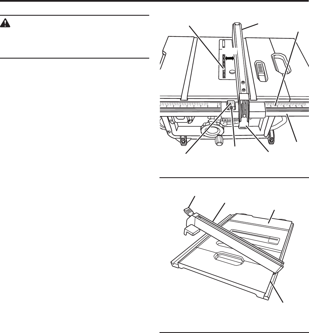
TO SET THE RIP FENCE SCALE INDICATOR
TO THE BLADE
See Figure 24.
Use the indicator on the rip fence to position the fence along
the scale on the front rail.
NOTE: The anti-kickback pawls and blade guard assembly
must be removed to perform this adjustment. Reinstall the
blade guard assembly when the adjustment is complete.
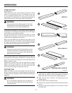
Begin with the blade at a zero angle (straight up).
Unplug the saw.
Loosen the rip fence by lifting the locking lever.
Using a framing square, set the rip fence 2 in. from the
blade tip edge.
Loosen the screw on the scale indicator.
Tighten the screw and check the dimension and the rip
fence.
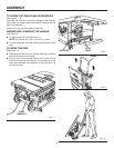
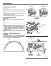
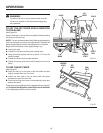
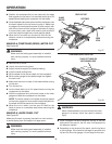
TO USE THE RIP FENCE
See Figure 25.
Place the rear lip on the rear of the saw table and pull
slightly toward the front of the unit.
Lower the front end of the rip fence onto the guide
surfaces on top of the front rail.
Push the locking lever down to automatically align and
secure the fence.
Check for a smooth gliding action. If adjustments are needed,
see To Check the Alignment of the Rip Fence to the Blade
in the Adjustment section of this manual.
BLADE
2 in.
RIP
FENCE
SCALE
LOCKING
LEVER
2 in.
MARK
SCREW
Fig. 25
Fig. 24