


35
ADJUSTMENTS
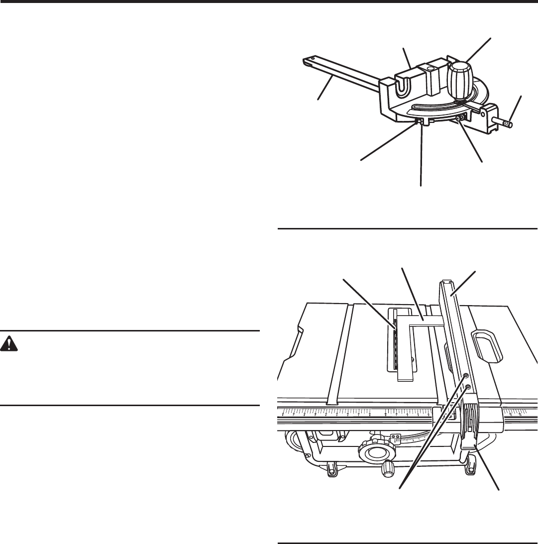
bLAdE
RIp FENCE
LOCKING
LEVER
SCREWS
LOCK
Nut
KNOb
MItER
GAuGE bASE
45° AdJuStAbLE
StOp SCREW
0° AdJuStAbLE
StOp SCREW
MItER
GAuGE ROd
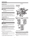
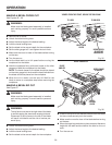
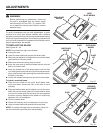
TO ADJUST THE MITER GAUGE
See Figure 47.
You can set the miter gauge at 0° and plus or minus 45° with
the miter gauge stop pin and adjustable stop screws.
NOTE: The miter gauge provides close accuracy in
angled cuts. For very close tolerances, test cuts are
recommended.
Loosen knob and pull out on stop pin to rotate miter
gauge base past stop screws.
Loosen the lock nut of the 0° stop screw at the stop pin
with a 8 mm wrench.
Place a 90° square against the miter gauge rod and the
miter gauge base.
If the rod is not square, loosen the knob, adjust the rod,
and tighten the knob.
Adjust the 0° stop screw until it rests against the stop
pin.
Adjust the plus and minus 45° stop screws using a 45°
triangle and the steps above.
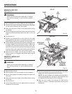
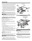
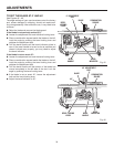
TO CHECK THE ALIGNMENT OF THE RIP
FENCE TO THE BLADE
See Figure 48.
WARNING:
To reduce the risk of injury, always make sure the
rip fence is parallel to the blade before beginning
any operation.
Unplug the saw.
Raise the locking lever to permit the rip fence to be
moved.
Place a framing square beside the blade and move the
rip fence up to the square. Take the dimension on the rip
scale.
Move the fence back and turn the framing square 180°
to check the other side.
If the two dimensions are not the same, loosen the two
screws on the fence and align it.
Retighten the two screws.
Make two or three test cuts on scrap wood. If the cuts
are not true, repeat the process.
FRAMING
SQuARE
Fig. 47
Fig. 48
StOp
pIN